Corsica V6-3100 3.1L VIN M SFI (1996)

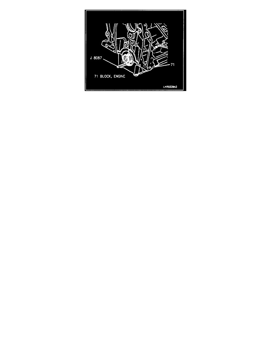
b. Measure the bore for taper and out of round using J 8087.
c. No taper or out of round should exist.
Measure
-
Bearing clearance. To determine the correct replacement insert size, the bearing clearance must be measured accurately. Either of the
following two methods may be used, however, method "A" gives more reliable results and is preferred.
Important
Method "A" yields measurements from which the bearing clearance can be computed. Method "B" yields the bearing clearance directly. Method
"B" does not give any indication of bearing run-out.
Do not mix inserts of different nominal size in the same bearing bore.
Method "A"
1. Measure the crankshaft journal diameter with a micrometer in several places, approximately 9O° apart, and average the measurements.
2. Measure taper and run-out.
3. Install bearing inserts and tighten rod and main bearing cap bolts to specification.
4. Measure inside bearing diameter of crankshaft bores with an inside micrometer.
-
Subtract the crankshaft journal diameter from the crankshaft bearing bore diameter to determine crankshaft bearing clearance.
5. Measure the inside bearing diameter of the connecting rod in the same direction as the length of the rod.
-
Subtract the connecting rod journal diameter from the connecting rod bearing bore diameter to determine connecting rod bearing clearance.
Important
-
The bearing cap must be tightened to specification when the measurement is taken.
-
Select a suitable set of inserts to provide specified clearance limits. If the specified clearances cannot be met, the crankshaft journal must be
reconditioned and undersized bearing inserts installed.
Method "B"
1. Clean and install the used bearing inserts.
2. Place a piece of gaging plastic across the entire bearing width.
Note: In order to prevent the possibility of cylinder block and/or main bearing cap damage, the main bearing caps are to be tapped into their
cylinder block cavity using a brass or leather mallet before attaching bolts are installed. Do not use attaching bolts to pull main bearing caps into
their seats. Failure to observe this information may damage a cylinder block or bearing cap.
3. Seat the bearing cap carefully by tapping it lightly with a suitable tool.
4. Tighten bearing cap bolts to specification.
Important
