
Corvette V8-7.0L (2007)
Step 1 - Step 10
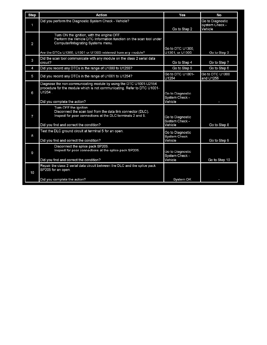
The numbers below refer to the step numbers on the diagnostic table.
2. A current DTC U1305 may be retrieved only from the body control module (BCM).
3. A partial malfunction in the class 2 serial data circuit uses a different procedure from a total malfunction of the class 2 serial data circuit. The
following modules communicate on the class 2 serial data circuit. The BCM is diagnosed only through GMLAN serial data circuit.
* Body control module (BCM)
* Communication interface module (OnStar(R))
* Digital radio receiver (DRR)
* Driver door module (DDM)
* Driver door switch (DDS)
* Driver position module (DPM)
* Folding top controller (FTC)
* Head up display (HUD)
* HVAC control module
* Inflatable restraint sensing and diagnostic module (SDM)
* Instrument panel cluster (IPC)
* Passenger door module (PDM)
* Radio
* Remote control door lock receiver (RCDLR)
* Steering column lock control module (SCLCM)
7. Data link connector terminals 2 and 5 provide the connection to the class 2 serial data circuit and the signal ground circuit respectively.
9. A poor connection at splice pack SP205 will cause this condition but will not set a DTC.
10. An open in the class 2 serial data circuit between the DLC and splice pack SP205 will prevent the scan tool from communicating with any module
on the class 2 network. This condition will not set a DTC.
Scan Tool Does Not Communicate with High Speed GMLAN Device