
Corvette V8-7.0L (2007)
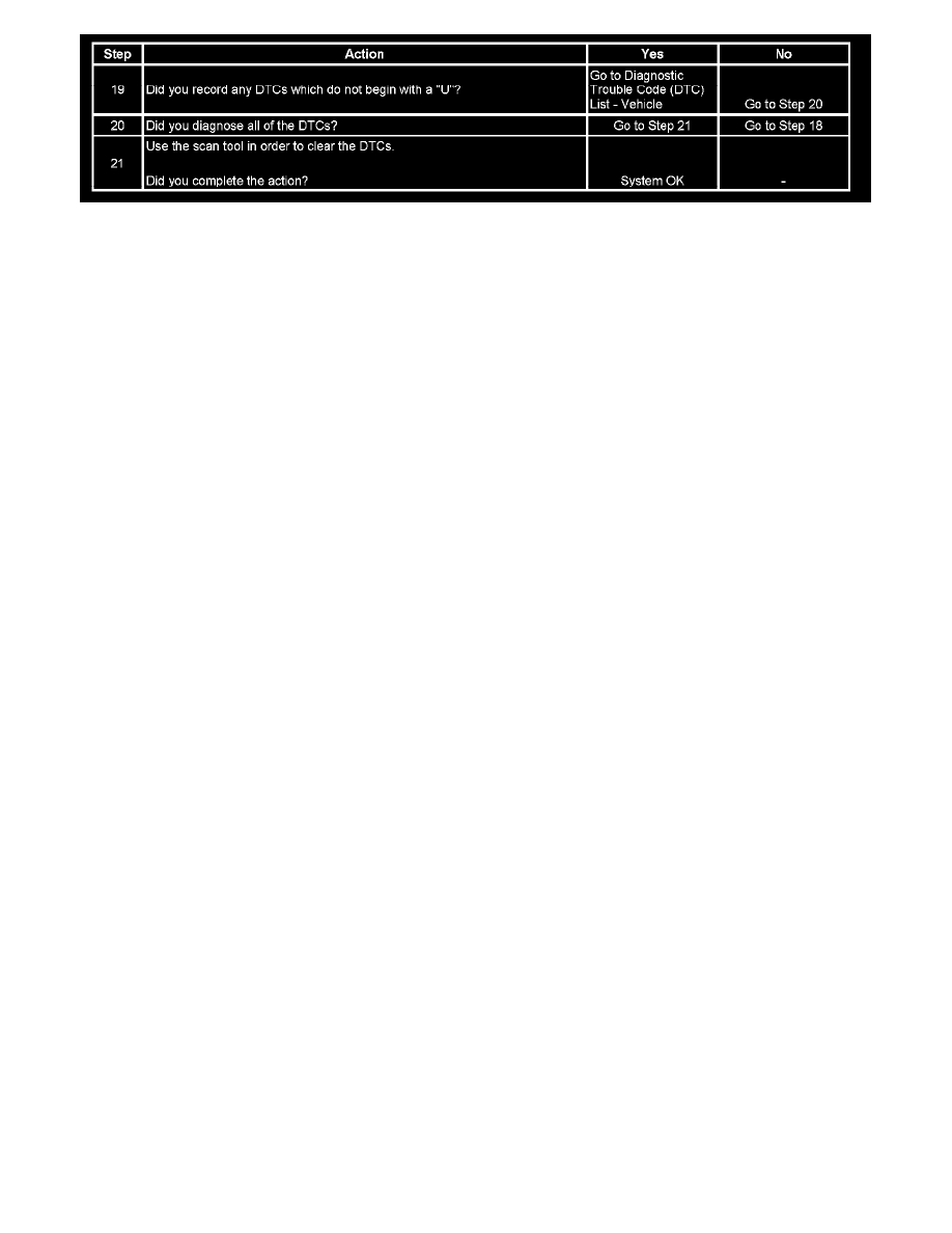
Step 19 - Step 21
The numbers below refer to the step numbers on the diagnostic table.
2. A partial malfunction in the high speed GMLAN serial data circuits uses a different procedure from a total malfunction of the high speed GMLAN
data circuits. The following modules communicate on the high speed GMLAN serial data circuits:
* Body control module (BCM)
* Communication interface module (OnStar(R))
* Electronic brake control module (EBCM)
* Electronic suspension control (ESC) Module
* Engine control module (ECM)
* Transmission control module (TCM)
8. Data link connector terminals 6 and 14 provide the connection to the GMLAN serial data high circuit and the GMLAN serial data low circuit
respectively.
15. If only one of the high speed GMLAN circuits is open all communication on the high speed bus will be disrupted.
19. The communication malfunction may have prevented diagnosis of the customer complaint.
Scan Tool Does Not Power Up
Scan Tool Does Not Power Up
Diagnostic Fault Information
Perform the Diagnostic System Check - Vehicle prior to using this diagnostic procedure. See: Testing and Inspection/Initial Inspection and Diagnostic
Overview/Diagnostic Starting Point - Vehicle
Circuit/System Description
The data link connector (DLC) is a standardized 16 cavity connector. Design and location is dictated by an industry-wide standard. The following is
required to be provided:
* Scan tool power battery positive voltage at terminal 16.
* Scan tool power ground at terminal 4.
* Common signal ground at terminal 5.
The scan tool will power up with the ignition OFF. Some modules, however, will not communicate unless the ignition is ON and the power mode master
(PMM) module sends the appropriate power mode message.
Circuit/System Verification
1. Ignition OFF, test for less than 1 ohm of resistance between terminal 4 at the data link connector (DLC) and ground.
‹› If greater than the specified value, test the ground circuit for an open/high resistance.
2. Ignition OFF, test for less than 1 ohm of resistance between the DLC terminal 5 and ground.
‹› If greater than the specified value, test the ground circuit for an open/high resistance.
3. Ignition ON, test for B+ between the DLC terminals 16 and ground.
‹› If not the specified value, test the B+ circuit for a short to ground or an open/high resistance.
4. If all circuits test normal, refer to the scan tool user guide.
Repair Instructions