
EL Camino V6-229 3.8L (1982)
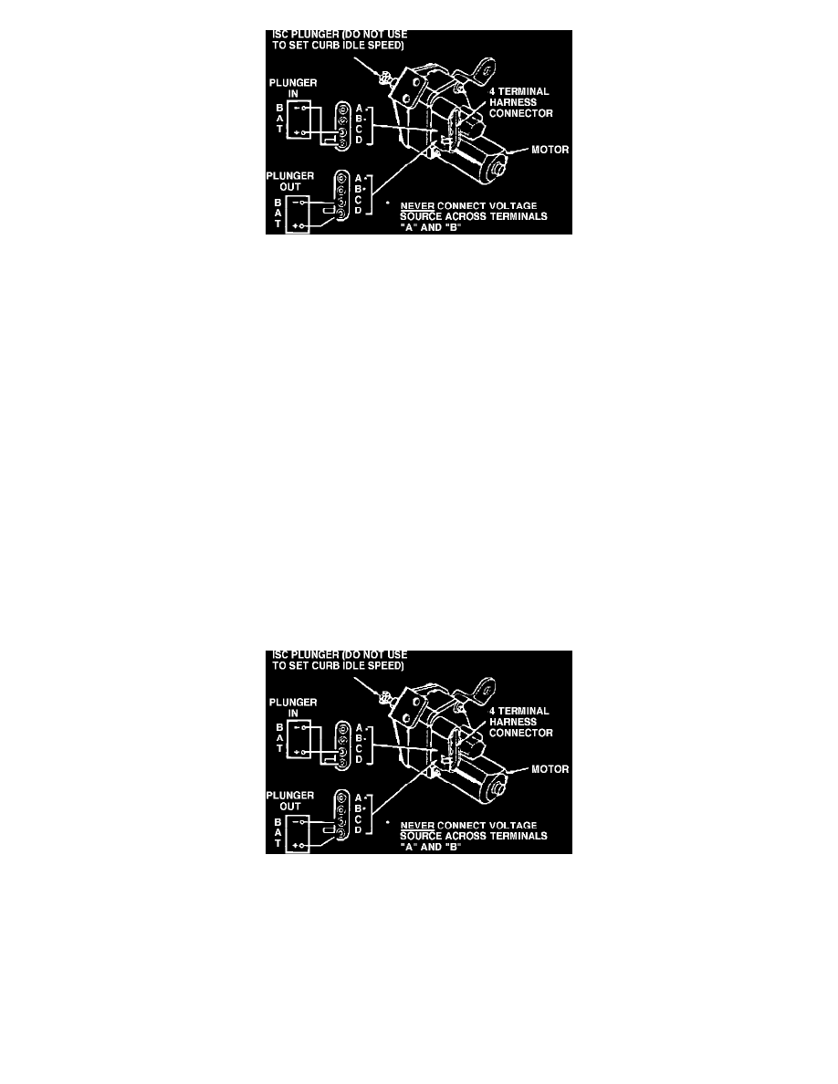
Idle Speed Control Assembly - Typical
CAUTION: DO NOT disconnect or connect ISC connector with ignition "ON" as damage to the ECM may occur.
1. Perform preliminary procedures - see emission label for latest instructions.
2. Before starting engine, place transmission in PARK (AUTO trans.) or NEUTRAL (MANUAL transmission), set parking brake, and block drive
wheels.
3. Connect dwell meter to mixture control (M/C) solenoid dwell lead. Remember to set dwell meter on the six cylinder scale, regardless of the engine
being tested.
4. Turn A/C "OFF".
5. Start engine and run until stabilized and in "closed loop" mode (dwell meter needle starts to vary).
6. Turn ignition "OFF".
CAUTION: Do not unplug ISC connector with ignition "ON" as damage to motor will occur.
7. Unplug connector from ISC motor.
8. Fully retract ISC plunger by applying 12 volts to terminal "C" and grounding lead to terminal "D" of the ISC motor connection.
CAUTION: DO NOT leave battery voltage applied to motor longer than necessary to retract ISC plunger. Prolonged contact will damage motor.
Also, NEVER connect voltage source across terminal "A" and "B" as damage to the internal throttle contact switch will result.
9. Start engine and run until dwell meter needle starts to vary, indicating "closed loop" operation.
10. Place A.T. transmission in Drive.
11. With ISC plunger fully retracted, adjust carburetor base (slow) idle stop screw (minimum authority) to the RPM shown in the carburetor charts.
12. PLACE TRANSMISSION IN PARK (AUTO TRANS.) OR NEUTRAL (MANUAL TRANS.).
Idle Speed Control Assembly - Typical
13. Fully extend ISC Plunger by applying 12 volts to terminal "D" and grounding lead to terminal "C" of the ISC Motor Connection. Leave power
applied only long enough to extend the plunger.
14. Manual transmission: Using Tool J-29607 or BT-8022 or equivalent, turn ISC Plunger to obtain ISC adjustment RPM (Maximum Authority)
shown in carburetor charts.
15. Automatic Transmission:
a. With transmission in PARK, using Tool J-29607, BT-8022 or equivalent, preset ISC plunger to obtain 1500 RPM.
b. With parking brake set and drive wheels blocked, place transmission in drive. Using Tool J-29607 or BT-8022 or equivalent, turn ISC Plunger
to obtain ISC adjustment RPM (Maximum Authority) shown in carburetor charts.