
Express 1/2 Ton Van V8-5.7L VIN R (1999)
Wheel Speed Sensor: Service and Repair
REMOVAL PROCEDURE
IMPORTANT:
^
The wheel speed sensor and splash shield are replaced as one part. Do not attempt to separate and reattach the sensor from the splash shield.
^
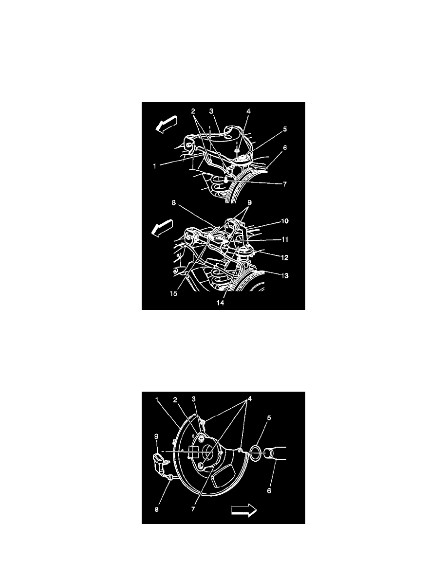
This vehicle is equipped with a either a 7300 lbs. GVW (C6A), 7700 lbs. GVW (C3F) or 8600 lbs. GVW (C6P) suspension system. The 7300 lbs.
vehicle uses a stamped/welded upper control arm, and the 7700 lbs. and 8600 lbs. vehicles use a steel bar type upper control arm. The wheel speed
sensor harness wire is attached and routed over the upper control arm in two different ways. Careful attention to these differences should be noted
before removing any components, to assure proper reassembly.
1. Raise and support vehicle.
2. Remove the tire and wheel.
3. Remove the brake caliper.
4. Remove the hub and rotor.
5. Disconnect the wheel speed sensor electrical connector and detach the rosebud clip from the frame.
IMPORTANT: Notice the position of the sensor wire clip on the shock tower. The sensor wire clip must be reinstalled in the same position, at
approximately 45° angle to the centerline of the vehicle.
6. Remove bolt (9,15) and washer which attaches the sensor wire clip at the shock tower.
7. Remove the rosebud clip (2) on upper control arm (3) (7300 lbs. GVW (C6A) only).
8. Remove the bolt (7,14) and nut (4,11) which attaches the sensor wire clip (2,9) at the upper ball joint (5,12).