
Express 1/2 Ton Van V8-5.7L VIN R (1999)
Refrigerant: Service and Repair
Recovering The Refrigerant
1. Connect a battery charger in order to prevent battery drain.
IMPORTANT: Use only the 23 kg (50 lb) unit refrigerant tank (J 39500-50) designed for the ACR4. The calibration of the unit overfill
limitation mechanism is specific for use with this tank. The tank valving is specific for use with the unit.
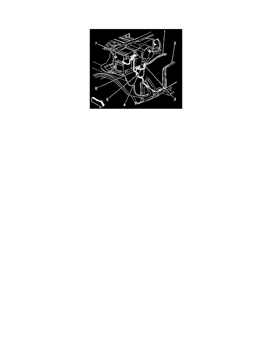
2. Attach the red high-side hose with the quick disconnect coupler to the high-side refrigerant service valve fitting (7) of the vehicle A/C system.
This valve is in the receiver dehydrator tube, between the receiver and dehydrator and the condenser.
3. Open the high-side coupler valve.
4. Attach the blue low-side hose with the quick disconnect coupler to the low-side refrigerant charge valve fitting (3) of the vehicle A/C system. This
valve is located between in the compressor and condenser hose, between the compressor and the expansion (orifice) tube.
5. Open the low-side coupler valve.
IMPORTANT: If the A/C system has no refrigerant, do not continue with the recovery operation. A recovery operation without refrigerant draws
air into the recovery tank.
6. Observe the high-side gauge and the low-side gauge on the unit control panel in order to be sure the A/C system has pressure.
No pressure indicates that the system has no refrigerant in need of recovery.
7. Open both the high-side and the low-side valves on the control panel.
8. Open both the red LIQUID and the blue GAS valves on the tank.
9. Slowly open the oil drain valve in order to determine whether the oil separator contains oil.
10. Drain any oil present in the separator into the catch bottle at the bottom of the unit.
11. Close the oil drain valve.
12. Dispose of the oil in the catch bottle in an appropriate manner.
Return the bottle in place on the unit.
13. Plug the unit into the proper voltage outlet.
14. Activate the MAIN POWER switch.
15. Start the engine.
16. With the A/C system in the ON position in order to stabilize the system, idle the engine for a period of one minute.
17. Turn the ignition switch to the OFF position.
18. Connect a battery charger in order to prevent battery drain.
19. Turn the ignition switch to the RUN position.
IMPORTANT: The blower motor in the HIGH setting increases the rate at which the J 39500-B recovers refrigerant. Maintain the A/C blower
motor on the HIGH setting during the recovery operation.
20. Turn the blower motor switch to the HIGH position.
21. Press the RECOVER key on the keypad.
22. Observe the cleaning process, which is 30-180 seconds in duration.
The unit clears itself of refrigerant.
The display reads CL-L.
23. When the cleaning is complete, the unit automatically starts the recover. The control panel shows that the unit is in the RECOVER mode of the
AUTOMATIC cycle.
24. The compressor automatically ceases operation when the initial recovery occurs at a vacuum of approximately 57 kPa (17 in. of Hg).
IMPORTANT: