
Express 1/2 Ton Van V8-5.7L VIN R (1999)
2. Touch the other lead to various points along the circuit where voltage should be present.
3. When the bulb illuminates, there is voltage at the point being tested.
Probing Electrical Connectors
IMPORTANT: Always be sure to reinstall the Connector Position Assurance (CPA) and Terminal Position Assurance (TPA) when reconnecting
connectors or replacing terminals.
Frontprobe
Disconnect the connector and probe the terminals from the mating side (front) of the connector.
NOTE: Do not insert test equipment probes into any connector or fuse block terminal. The diameter of the test probes will deform most terminals.
A deformed terminal can cause a poor connection, which can result in system failures. Always use the J 35616-A Connector Test Adapter Kit or
the J 42675 Flat Wire Probe Adapter Kit in order to frontprobe terminals. Do not use paper clips or other substitutes as they can damage terminals
and cause incorrect measurements.
Backprobe
Do not disconnect the connector and probe the terminals from the harness side (back) of the connector.
IMPORTANT:
^
Backprobe connector terminals only when specifically required in diagnostic procedures.
^
Do not backprobe a sealed (Weather Pack (R)) connector, less than a 280 series Metri-Pack connector, a Micro-Pack connector, or a flat wire
(dock and lock) connector.
^
Backprobing can be a source of damage to connector terminals. Use care in order to avoid deforming the terminal, either by forcing the test
probe too far into the cavity or by using too large of a test probe.
^
After backprobing any connector, inspect for terminal damage. If terminal damage is suspected test for proper terminal contact.
Connector Test Adapters
NOTE: Do not insert test equipment probes into any connector or fuse block terminal. The diameter of the test probes will deform most terminals. A
deformed terminal can cause a poor connection, which can result in system failures. Always use the J 35616-A Connector Test Adapter Kit or the J
42675 Flat Wire Probe Adapter kit in order to frontprobe terminals. Do not use paper clips or other substitutes as they can damage terminals and cause
incorrect measurements.
Fused Jumper Wires
IMPORTANT: A fused jumper may not protect solid state components from being damaged.
The J 36169-A fused jumper includes small clamp connectors that provide adaptation to most connectors without damage. This fused jumper wire is
supplied with a 20 A fuse which may not be suitable for some circuits. Do not use a fuse with a higher rating than the fuse that protects the circuit being
tested.
Repairing Damaged Wire Insulation
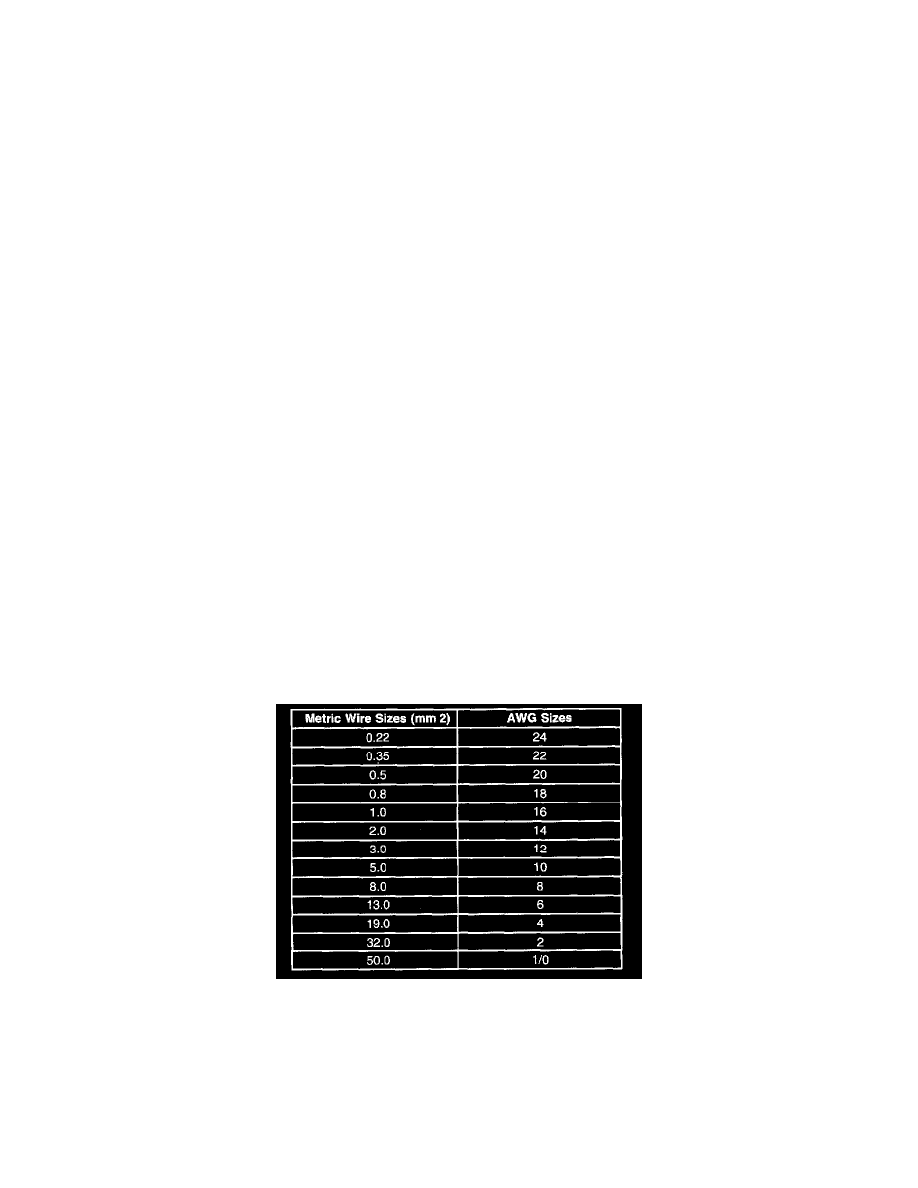
Wire Size Conversion Table
If the conductive portion of the wire is not damaged, locate the problem and apply tape around the wire. If the damage is more extensive, replace the
faulty segment of the wire. Refer to Splicing Copper Wire Using Splice Clips and follow the instruction to repair the wire. See: Wiring
Repairs/Splicing Copper Wire Using Splice Clips
Fuses