
Express 1/2 Ton Van V8-5.7L VIN R (1999)
Repair and Verify Fix
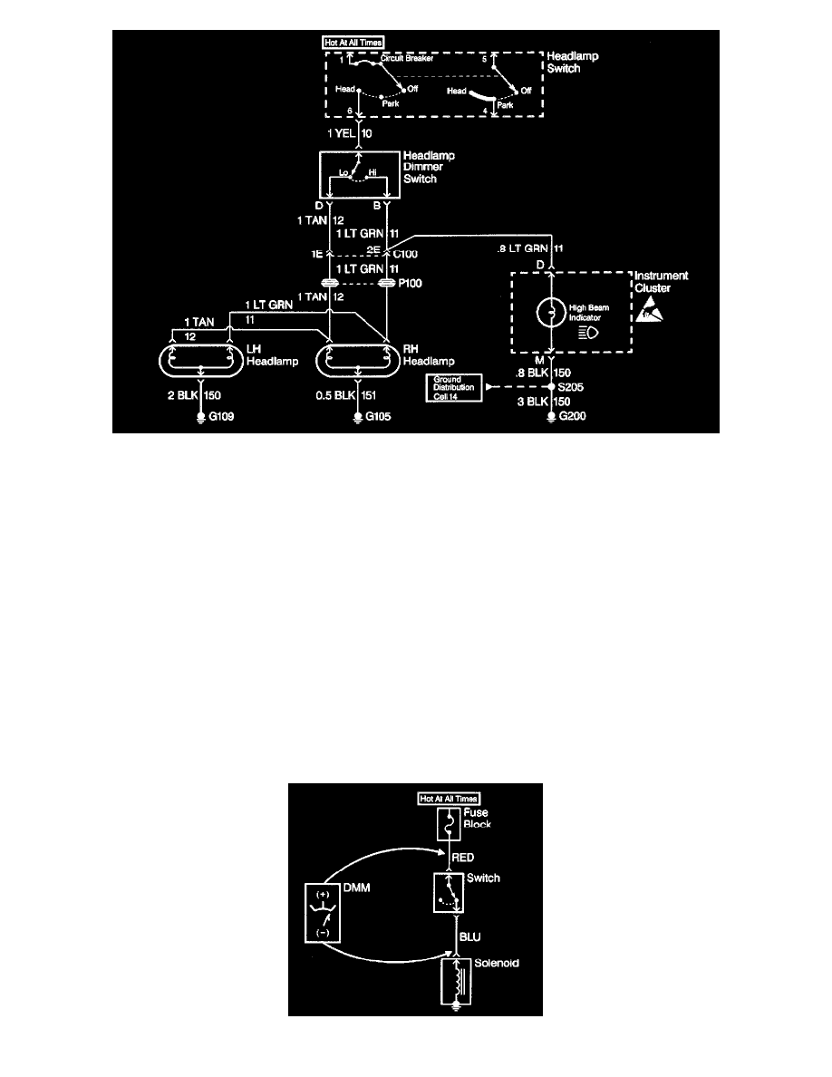
From isolating the root cause, basically the problem has been diagnosed. Using the Component Location Table and the corresponding figure,
quickly find C100 and the LT GRN wire, locate the exact trouble point and make the repair.
Check the thoroughness of the repair by performing a final system check on the headlamp circuit. This of course means making sure that both high
beams, both low beams, and the high beam indicator are working.
Measuring Voltage
NOTE: Refer to Test Probe Notice in Cautions and Notices.
The following procedure measures the voltage at a selected point in a circuit.
1. Apply power to the circuit.
2. Set the rotary dial of the DMM into the V (AC) or V (DC) position.
3. Connect the positive lead of the DMM to the point of the circuit to be tested.
4. Connect the negative lead of the DMM to a good ground.
5. Operate the circuit.
6. The DMM displays the voltage measured at that point.
Measuring Voltage Drop
NOTE: Refer to Test Probe Notice in Cautions and Notices.
The following procedure determines the difference in voltage potential between two points.