
Express 1/2 Ton Van V8-5.7L VIN R (1999)
Arming Sensor: Service and Repair
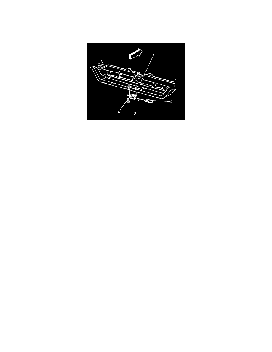
Front End Discriminating Sensor Replacement
Removal Procedure
Caution: Be careful when you handle a sensor. Do not strike or bit a sensor. Before applying power to a sensor:
^
Remove any dirt, grease, etc. from the mounting surface.
^
Position the sensor horizontally on the mounting surface.
^
Point the arrow on the sensor toward the front of the vehicle.
^
Tighten all of the sensor fasteners and sensor bracket fasteners to the specified torque value.
Failure to follow the correct procedure could cause air bag deployment, personal injury, or unnecessary SIR system repairs.
Removal Procedure
1. Disable the SIR system.
2. Raise the vehicle and support the vehicle with safety stands.
3. Remove the Connector Position Assurance (CPA) from the Inflatable Restraint front end discriminating sensor harness connector.
4. Disconnect the Inflatable Restraint Front End Discriminating Sensor harness connector from the sensor.
5. Remove the Inflatable Restraint Front End Discriminating Sensor mounting fasteners (4).
6. Remove the Inflatable Restraint Front End Discriminating Sensor (3) from the front end lower tie bar (1).
Important: Utilize the first fastener repair and the second fastener repair in the event that the sensor mounting holes or fasteners are damaged to the
extent that the sensor can no longer be properly mounted.
7. Perform the following steps in order to complete the first fastener repair:
7.1. Remove the stripped fastener and discard the nut.
7.2. Chisel off the damaged weld nut and discard the weld nut.
7.3. Condition the front end lower tie bar surface where the new weld nut is to be installed.
7.4. Install new weld nut GM P/N 11514034 into position.
7.5. Migweld the new weld nut to the front end lower tie bar surface in the correct location.
Notice: Refer to Fastener Notice in Cautions and Notices.
7.6. Install sensor with new fastener GM P/N 11515926.
Tighten
Tighten fastener to 10 N.m (89 lb in).
8. Perform the following steps in order to complete the second fastener repair:
8.1. Remove the improperly installed rivet.
8.2. Enlarge the mounting holes in the lower radiator support to 9.0 mm(0.35 in).
8.3. Insert and properly seat the rivnut.
Notice: Refer to Fastener Notice in Cautions and Notices.
8.4. Install the sensor with the screw.
Tighten
Tighten the fasteners to 8.0 N.m(71 lb in).