
Express 1/2 Ton Van V8-5.7L VIN R (1999)
Alignment: Service and Repair
Frame Bracket Knock Out Removal
REMOVAL PROCEDURE
-
Tools Required
-
J 38794 Knockout Removal Tool
IMPORTANT: As originally installed, the upper control arm cannot be adjusted for caster or camber. If the caster and camber is out of
specifications, the caster and camber can be set to the right specifications.
1. Raise the vehicle. Suitably support the vehicle with safety stands.
IMPORTANT: The safety stands must remain under the lower control arms during the removal and the installation in order to retain the lower
control arm position.
2. Support the lower control arms with a suitable lack stand.
3. Remove the tire and the wheel from the vehicle.
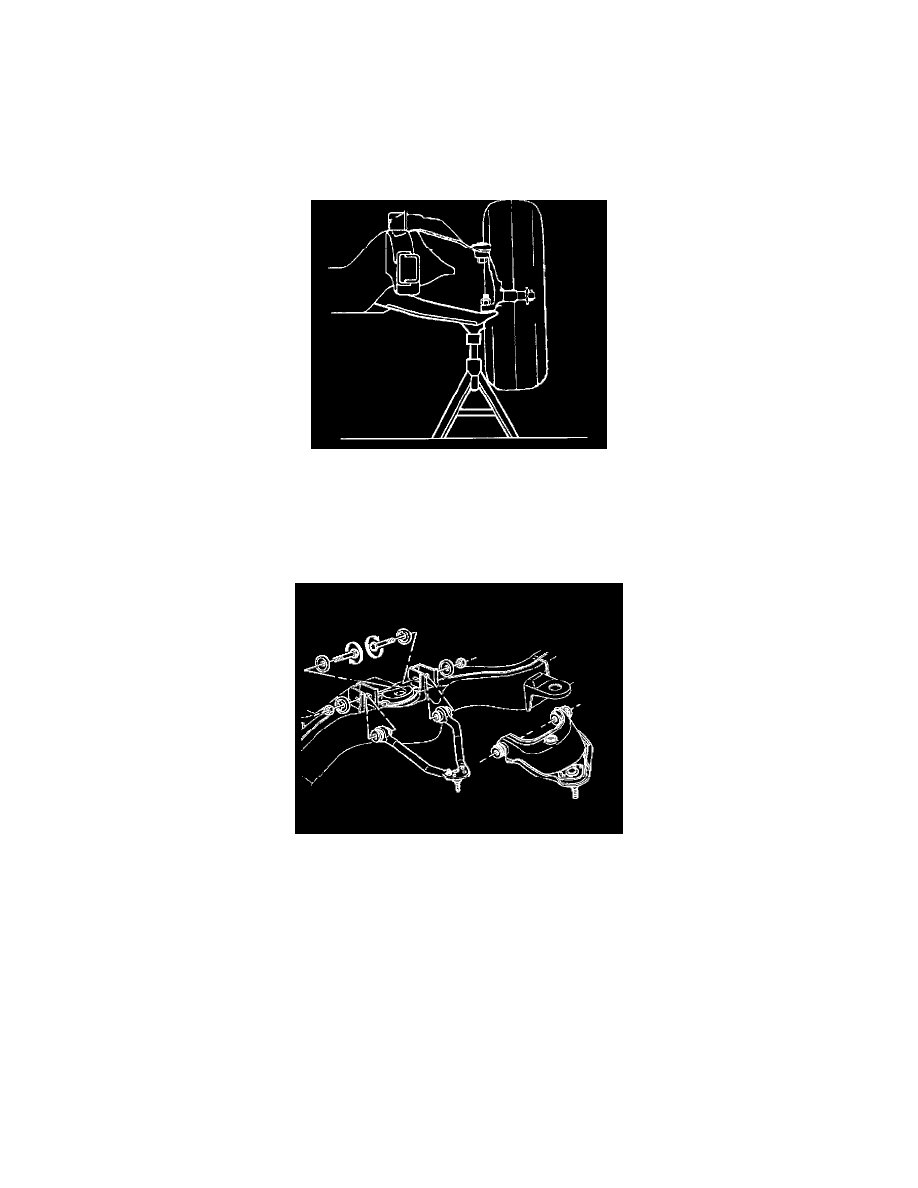
4. Remove the upper control arm from the frame bracket. Refer to Upper Control Arm Replacement.
5. Move the upper control arm up and to the side to gain access to the frame bracket.
6. Install the knockout tool using the J 38794 in order to remove the frame bracket knockout as follows:
-
Do not distort the frame bracket when removing the knockout.
-
The forward bracket requires the bridge to be installed between the legs of the bracket due to access problems.
-
Apply extreme pressure lubricant to the threads of the T-bolt and insert the bolt through the knockout hole in the bracket support.
-
Insert the bolt through the knockout hole in the bracket support.
NOTICE: Do not subject the tool to more than 100 Nm (75 ft. lbs.) torque. Exceeding the recommended torque may damage the tool and/or the
bracket.
7. Remove any wax coatings in the knockout area in order to make the stamped outline visible for removing.
8. Assemble the following parts in order:
-
The bridge.
-
The bearing with the chamfered side out.
-
The washer.