
Express 2500 V8-6.6L DSL Turbo (2010)
12. Snap the wiring harness in place on the valve body bolts. Ensure the harness loom tab is located under the transmission fluid pressure (TFP)
switch.
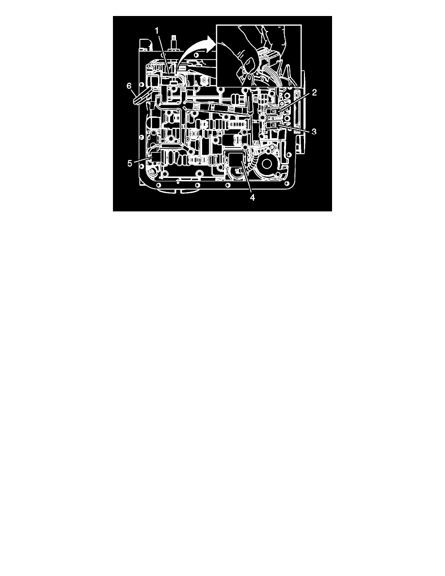
13. Install the wiring connectors to the electrical components (1-6) as indicated in the following list:
1. The manual shift detent lever with shaft position switch assembly
2. The 1-2 shift solenoid
3. The 2-3 shift solenoid
4. The pressure control solenoid (PCS)
5. The TCC PWM solenoid
6. The input speed sensor (ISS)
14. Install the transmission oil pan and filter. Refer to Automatic Transmission Fluid and Filter Replacement (See: Service and Repair/Removal and
Replacement/4L60-E/4L65-E/4L70-E - Automatic Transmission/Automatic Transmission Fluid and Filter Replacement).
15. Lower the vehicle.
16. Fill the transmission to the proper level with DEXRON(R) VI transmission fluid. Refer to Transmission Fluid Level and Condition Check (See:
Testing and Inspection/Component Tests and General Diagnostics/4L60-E/4L65-E/4L70-E - Automatic Transmission/Transmission Fluid Level
and Condition Check).
Note: It is recommended that transmission adaptive pressure (TAP) information be reset.
Resetting the TAP values using a scan tool will erase all learned values in all cells. As a result, the engine control module (ECM), powertrain
control module (PCM) or transmission control module (TCM) will need to relearn TAP values. Transmission performance may be affected as new
TAP values are learned.
17. Reset the TAP values. Refer to Transmission Adaptive Functions (See: Description and Operation/4L60-E/4L65-E/4L70-E - Automatic
Transmission/Transmission Adaptive Functions).