
Express 2500 2WD V8-4.8L VIN V (2004)
Steps 19-20
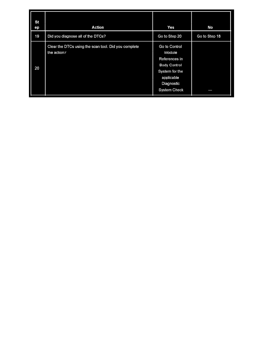
The numbers below refer to the step numbers on the diagnostic table.
2. A partial loss of communication in the class 2 serial data circuit uses a different procedure than a total loss of communication of the class 2 serial
data circuit.
4. The following DTCs may be retrieved with a history status. These DTCs are not the cause of the present condition.
-
U1300
-
U1301
-
U1305
6. A State of Health DTC with a history status may be present along with a U1000 or U1255 with a current status. This indicates that the malfunction
occurred when the ignition was on.
10. Normal class 2 serial data communication cannot take place until the body control module (BCM) sends the appropriate power mode message. If
the BCM does not send a wake-up message, other modules on the class 2 serial data circuit may not communicate. Early 2004 model vehicles have
a redundant class 2 serial data circuit between the BCM and PCM. Late 2004 model vehicles do not have this circuit and it is not necessary to
disconnect the PCM to perform this step.
12. Normal class 2 serial data communication cannot take place until the body control module (BCM) sends the appropriate power mode message. If
the BCM does not send a wake-up message, other modules on the class 2 serial data circuit may not communicate.
17. If there are no current DTCs that begin with the letter "U", the communication concern has been repaired.
18. The communication concern may have prevented diagnosis of the customer complaint.
Scan Tool Does Not Power Up
SCAN TOOL DOES NOT POWER UP
CIRCUIT DESCRIPTION
The data link connector (DLC) is a standardized 16 cavity connector. Connector design and location is dictated by an industry wide standard, and is
required to provide the following:
-
Scan tool power battery positive voltage at terminal 16
-
Scan tool power ground at terminal 4
-
Common signal ground at terminal 5
The scan tool will power up with the ignition OFF. Some modules however, will not communicate unless the ignition is ON and the power mode
master (PMM) module sends the appropriate power mode message.
TEST DESCRIPTION