
G 1500 1/2 Ton Van V6-4.3L VIN W (1997)
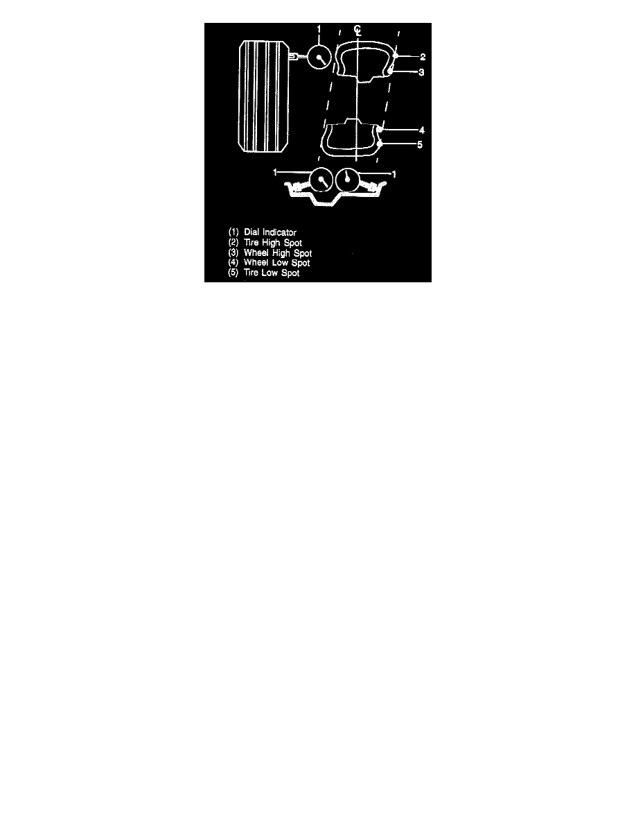
Lateral runout is a sideways variation causing a twist or wobble and is measured on a side surface. On the tire and wheel assembly, measure the sidewall
of the tire as close to the tread shoulder design edge as possible. The total runout is the reading from the gage, and the high spot is the location of the
maximum runout. On a rim, if either flange is beyond guidelines, replace the rim.
-
Aluminum Wheels - 0.762 mm (0.030 inches).
-
Steel Wheels - 1.143 mm (0.045 inches).
Measurement Procedures
1. Inflate the tires to specifications.
2. Warm up the tires prior to taking measurements to eliminate flat spotting.
-
Newly installed tires usually do not require warming up.
3. Raise the vehicle on a lift.
-
If measurements will be taken off the vehicle, mount each tire and wheel assembly on a dynamic balance machine.
4. Mark the tire and wheel for exact replacement.
a. Mark a wheel hub bolt and its exact position on the wheel.
b. Mark each tire and wheel for replacement on the exact hub and rotor.
5. Take either a radial or lateral runout measurement.
a. Place the dial indicator in position.
b. Rotate the tire and wheel assembly (or just the wheel) to find its low spot. Adjust the dial indicator to read zero.
c. Rotate it again to verify the low spot of the dial indicator. The dial indicator must return to zero.
d. Disregard any instantaneous dial jumps due to welds, paint runs, scratches, etc. on the wheel.
e. Rotate the tire and wheel (or just the wheel) and note the amount of runout from zero. Locate and mark on the high spot.
6. If there is a large difference in runout measurements from on vehicle to off vehicle, the runout problem is likely due to excessive runout of the bolt
circle or hub.
7. If measured runouts are not within the guidelines (located in "Specifications" at the end of this section), proceed to "Vectoring" to correct the
problem.
Description
Vectoring is a technique used to reduce radial or lateral runout and to even dynamic balance on the tire and wheel assemblies. Vectoring can be
accomplished by the positioning of the tire on the hub and rotor.
Important: Always re-balance the tire and wheel after vectoring.
Tire to Wheel Vectoring