
G 30 Van V6-262 4.3L VIN Z (1992)
NOTICE:
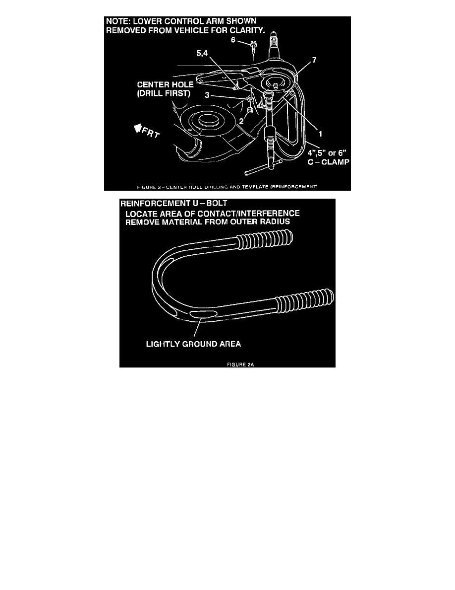
When correctly installed, U-bolt will be about even with bottom of ball joint. U-bolt is NOT designed to fit into galley of control arm. On
some vehicles, U-bolt may contact flange edge of control arm and interfere with correct installation. If this happens, locate and mark area
where U-bolt comes in contact with control arm. You may remove only enough material (LIGHTLY grind) (Figure 2A) from OUTER radius
of U-bolt to allow clearance between U-bolt and control arm (Figure 2, Item 7).
5.
Drill a center hole with a 3/8 inch (9.5 mm) drill. Reinforcement has been designed to be used as a template. When drilling keep drill as
perpendicular as possible.
6.
Install a 3/8-16 bolt (Figure 2, Item 6), nut (Figure 2, Item 3) and washer (Figure 2, Item 2) in center hole and torque to approximately 18 N-m (13
lb.ft.).
7.
Remove "C" Clamp.
8.
Drill remaining holes in sequence.
9.
Disassemble reinforcement (Figure 2, Item 1) and U-bolt (Figure 2, Item 7) from control arm and remove all chips and burs from lower control
arm and reinforcement.
INSTALLATION OF REINFORCEMENT