
G 30 Van V8-379 6.2L DSL VIN C FI (1992)
3.
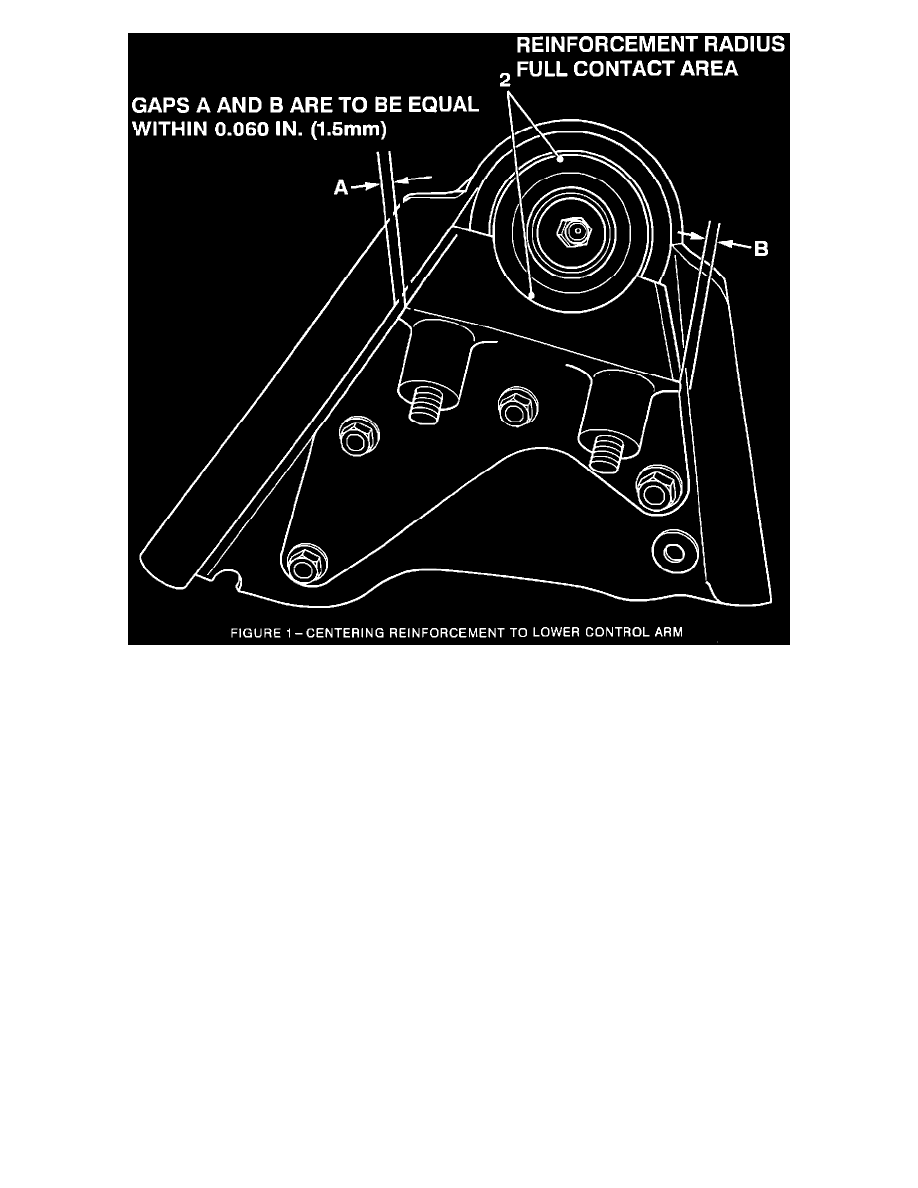
Center reinforcement between flanges (Figure 1). The technician may want to do one side at a time. Gaps A & B (Figure 1) are to be equal to
within 0.060 inch (1.5 mm) Secure reinforcement with a "C" clamp (Figure 2).
NOTICE:
Reinforcement is installed CORRECTLY when ball joint makes full contact with reinforcement radius (Figure 1, Item 2) not just in center
section of reinforcement.
Reinforcement is designed to fit ball joints with a bottom diameter of 2.60 inches (66 mm) or greater. Technician may find that ball joint does not
make full contact with radius of reinforcement when reinforcement is centered correctly between flanges.
It may be possible that an after market ball joint with a bottom diameter which is less than 2.60 inches (66 mm) has been installed. This does not
allow for full contact with the radius of the reinforcement. When this condition happens, only a small section of the ball joint will come in contact
with the reinforcement. If this occurs, make certain ball joint is clean as described in step 1 and measure bottom diameter of ball joint with a
caliper. If measurement is LESS THAN 2.60 INCHES (66 MM) the ball joint must be replaced with a GM ball joint.
If an after market lower control arm has been installed, it will be necessary to remove the aftermarket control arm, install a GM designed control
arm and perform the installation of the reinforcement per the campaign service procedure.
4.
Install U-bolt (Figures 1 & 3) and torque nuts to approximately 10 Nm (7 lb.ft.).
IMPORTANT:
This step must be performed before proceeding to step 5.