
G 30 Van V8-393 6.5L DSL VIN P (1995)
Positive Crankcase Ventilation: Description and Operation
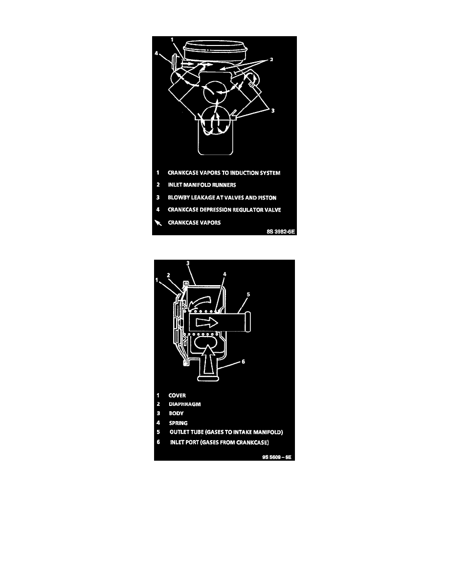
Crankcase Vapor Flow
CDR Valve Operation
DESCRIPTION
The crankcase ventilation system used on diesel engines is designed to maintain a slightly negative (vacuum) crankcase pressure across the speed
range. The system consists of a Crankcase Depression Regulator (CDR) valve, located on the right valve cover and the attaching vent hose/pipes
to the engine inlet system. The CDR valve is used only to regulate crankcase pressure between 0" and -4" water depression over the engine speed
range. The CDR valve IS NOT an oil separator or a crankcase effluent flow regulator. Hence, the CDR valve DOES NOT prevent oil droplets/mist
from entering the intake system, nor does it effect engine oil consumption.
The intake manifold vacuum acts against a spring loaded diaphragm to control the flow of crankcase gases. Higher intake vacuum (or high intake
restriction, e.g. plugged air filter) levels pull the diaphragm closer to the top of the outlet tube. This reduces the vacuum level from getting to high