
HHR L4-2.4L (2010)
Seat Heater: Testing and Inspection
Heated Seat Inoperative
Heated Seat Inoperative
Diagnostic Instructions
*
Perform the Diagnostic System Check - Vehicle (See: Testing and Inspection/Initial Inspection and Diagnostic Overview/Diagnostic System
Check - Vehicle) prior to using this diagnostic procedure.
*
Review Strategy Based Diagnosis (See: Testing and Inspection/Initial Inspection and Diagnostic Overview/Strategy Based Diagnosis) for an
overview of the diagnostic approach.
*
Diagnostic Procedure Instructions (See: Testing and Inspection/Initial Inspection and Diagnostic Overview/Diagnostic Procedure Instructions)
provides an overview of each diagnostic category.
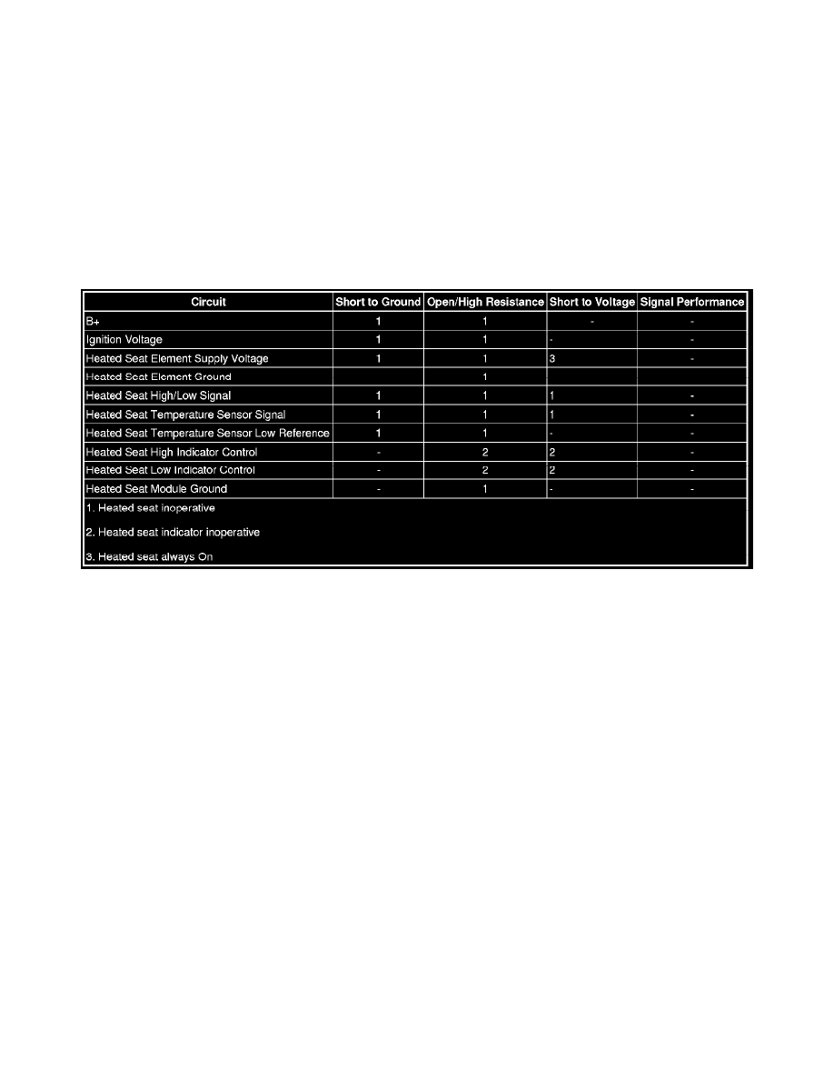
Diagnostic Fault Information
Circuit/System Description
Ignition voltage is supplied to the heated seat module (HSM) through the 10 A HTD SEAT Fuse 47 located in the underhood fuse block. This voltage is
used to power up the HSM. Battery positive voltage is supplied at all times to the HSM through the 20 A HTD/SEAT Fuse 23 also located in the
underhood fuse block. When commanded ON, the HSM uses this voltage to heat the seat heating elements. The HSM and the seat heating elements are
grounded through the module ground circuit to G301 and G302.
Each time the heated seat switch is pressed, B+ is supplied to the HSM through the heated seat signal circuit. The module counts these inputs to
determine what level of heat the vehicle operator is commanding. In response to these switch signals, the HSM applies B+ through the appropriate
heated seat switch indicator control circuits to the HVAC control module illuminating the temperature indicators. The HSM then closes it's contacts and
applies B+ through the heated seat element supply voltage circuit to the seat heating elements. When the thermistor inside the seat cushion reaches a
certain resistance, the HSM opens and closes the supply voltage in order to maintain that heat level.
Reference Information
Schematic Reference
Heated/Cooled Seat Schematics (See: Diagrams/Electrical Diagrams)
Connector End View Reference
Component Connector End Views (See: Diagrams/Connector Views)
Description and Operation
Heated Seats Description and Operation (See: Description and Operation)
Electrical Information Reference
*
Circuit Testing (See: Testing and Inspection/Component Tests and General Diagnostics/Circuit Testing/Circuit Testing)
*
Connector Repairs (See: Testing and Inspection/Component Tests and General Diagnostics/Connector Repairs/Connector Repairs)
*
Testing for Intermittent Conditions and Poor Connections (See: Testing and Inspection/Component Tests and General Diagnostics/Circuit
Testing/Testing for Intermittent Conditions and Poor Connections)
*
Wiring Repairs (See: Testing and Inspection/Component Tests and General Diagnostics/Wiring Repairs/Wiring Repairs)