
Impala V6-3.9L (2007)
205, harness side.
3. Ignition ON, with a scan tool, attempt to communicate with the BCM. Communication should be available.
‹› If no communication, test the following circuits: serial data circuit for a short to ground, a short to voltage or an open/high resistance between
the BCM and DLC, BCM voltage inputs for open/high resistance or short to ground, BCM grounds for open/high resistance. If the circuits test
normal, replace the BCM.
4. Install another 3-amp fused jumper wire to pin A of SP 205, harness side.
5. Use the other end of the jumper wire to connect all other pins, harness side, one at a time and verify that low speed communication remains
available to the BCM.
‹› If low speed communication is interrupted after connecting an individual module at SP 205, test the serial data circuit between SP 205 and the
last module connected for a short to ground and short to voltage. If the circuit tests normal, replace the module that caused no communication.
Repair Instructions
Perform the Diagnostic Repair Verification after completing the repair.
* Control Module References for module replacement, setup, and programming See: Testing and Inspection/Programming and Relearning
* GMLAN Wiring Repairs See: Testing and Inspection/Diagnostic Trouble Code Tests and Associated Procedures/Verification Tests and
Procedures
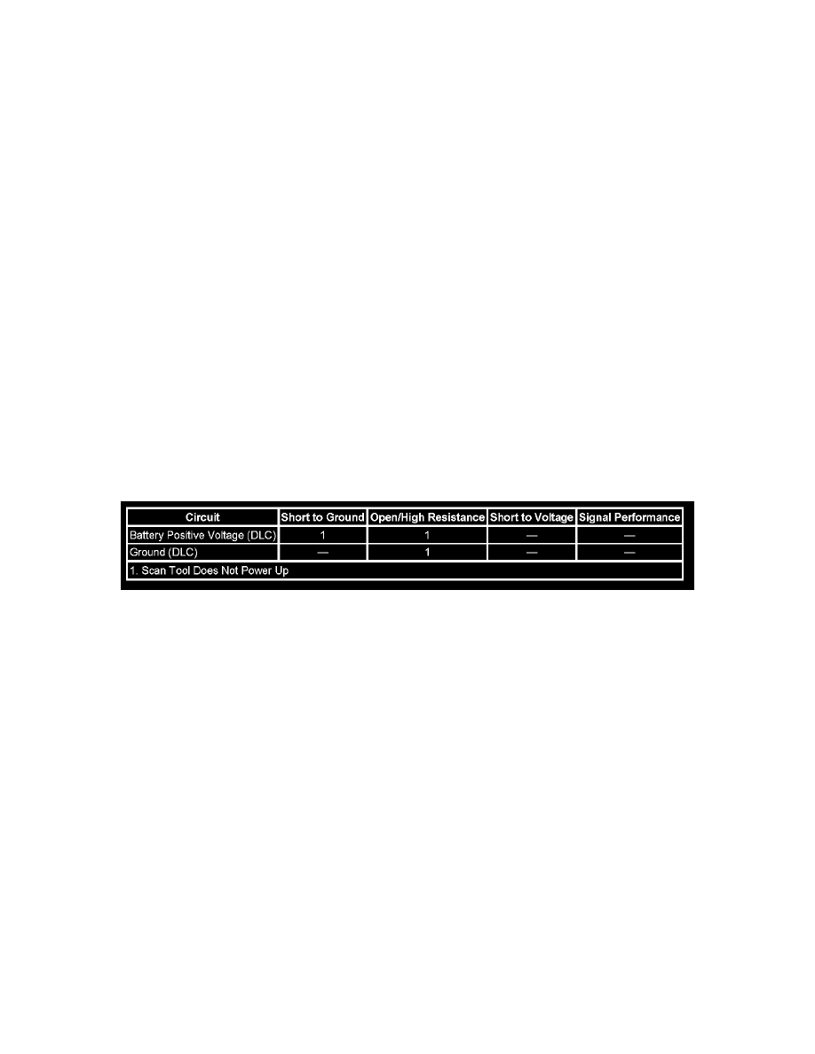
Scan Tool Does Not Power Up
Scan Tool Does Not Power Up
Diagnostic Fault Information
Perform the Diagnostic System Check - Vehicle prior to using this diagnostic procedure. See: Testing and Inspection/Initial Inspection and Diagnostic
Overview/Diagnostic Starting Point - Vehicle
Circuit/System Description
The data link connector (DLC) is a standardized 16 cavity connector. Connector design and location is dictated by an industry wide standard, and is
required to provide the following:
* Scan tool power battery positive voltage at terminal 16
* Scan tool power ground at terminal 4
* Common signal ground at terminal 5
Diagnostic Aids
* The scan tool will power up with the ignition OFF. Some modules however, will not communicate unless the ignition is ON and the power mode
master (PMM) module sends the appropriate power mode message.
* If the battery positive voltage, ground circuits and connections of the DLC are functioning properly, the malfunction must be due to the scan
tool/CANdi module.
* Use the DMM MIN/MAX function to capture/locate intermittent conditions.
Circuit/System Testing
1. Ignition ON, test for battery voltage between the battery positive voltage circuit of the DLC and ground.
‹› If less than battery voltage, repair the voltage supply circuit for a short to ground or an open/high resistance.
2. Test for less than 1.0 ohm of resistance between the ground circuit of the DLC and ground.
‹› If greater than 1.0 ohm, repair the ground circuit for an open/high resistance.