
Impala V8-5.3L (2008)
37. Repeat steps 35 and 36 for the opposite end of the splice.
38. Use a heat torch to apply heat to the center area of the sleeve while rotating and gradually moving to the open ends of the tubing. The tubing will
shrink completely as the heat is moved along the insulation. A small amount of sealant will come out of the end of the tubing when sufficient
shrinkage has occurred.
39. Repeat steps 34 through 38 for the:
-
Cooling Fan - Right Supply Voltage Circuit
-
Cooling Fan - Left Supply Voltage Circuit
40. Reinsert the High and Low Speed Cooling Fan Relay Control Circuit wires coming from the ECM back into the respective conduit for the harness
and tape as needed.
41. Route the new spliced High Speed and Low Speed Cooling Fan Relay Control Circuit wires under the fuse block and toward the RH fender flange.
42. Insert any excess wire length for the Cooling Fan Low Reference Circuit, Right Supply Voltage Circuit and Left Supply Voltage Circuit back into
the conduit (1) from which it was extracted in the area by the RH fender flange and tape as needed.
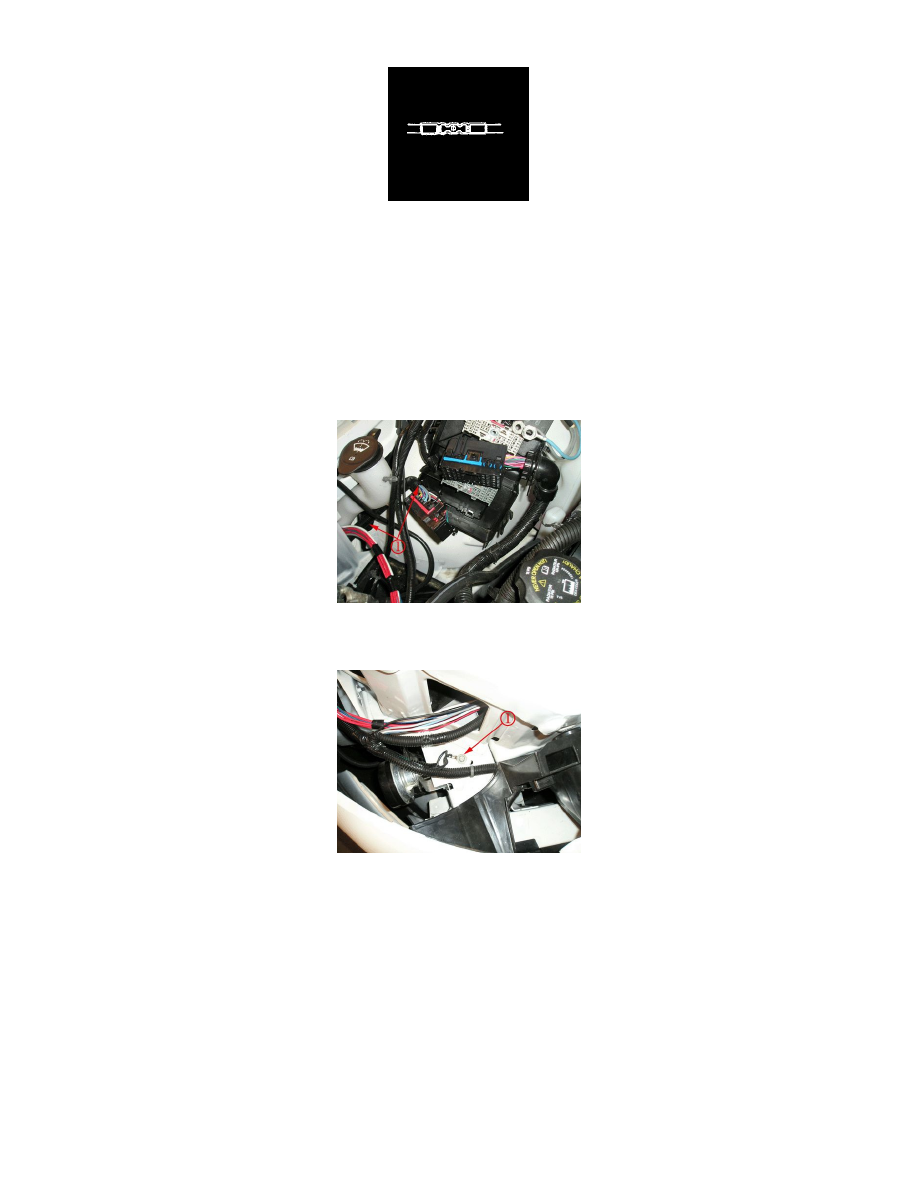
43. Install the ground wire grommet from the revised harness assembly at the existing G 100 ground location (1) as shown.
Tighten
Tighten the fastener to 7 Nm (62 lb in).
44. Install and seat the X1 and X3 electrical connectors into the fuse block. Verify the proper positioning of all four connectors in the fuse block.