
Impala V8-5.3L (2008)
Circuit/System Description
Modules connected to the high speed GMLAN serial data circuits monitor for serial data communications during normal vehicle operation. Operating
information and commands are exchanged among the modules when the ignition switch is in any position other than OFF. The high speed GMLAN serial
data circuits must be operational for the vehicle to start due to body control module (BCM) and engine control module (ECM) communications. The
vehicle theft deterrent (VTD) module and ECM exchange information using the BCM as the gateway module allowing communication between the high
and low speed serial data buses. The low speed GMLAN serial data circuit must also be operational for vehicle starting. The high speed GMLAN serial
data bus uses two 120 ohm terminating resistors that are in parallel with the high speed GMLAN (+) and (-) circuits. One of the resistors is internal to the
ECM and the other is either behind the left kick panel (w/o UE1) or in the rear compartment (UE1).
Diagnostic Aids
*
Communication may be available between the BCM and the scan tool with the high speed GMLAN serial data system inoperative. This condition
is due to the BCM using both the high and low speed GMLAN systems.
*
Use the Data Link References to identify the high speed GMLAN serial data modules.
*
This test is used for a total high speed GMLAN communication failure. If only 1 module is not communicating and sets no DTC, ensure that the
vehicle is equipped with the module, then use DTC U0100-U0299 for diagnostics.
*
An open in the DLC ground circuit terminal 5 will allow the scan tool to operate to set up the vehicle on the tool and then not communicate with
the vehicle. When the scan tool is to the point of communicating with the vehicle, a message on the scan tool will indicate "no CANdi module
detected" and will not communicate.
*
The engine will not start when there is a total malfunction of the high speed GMLAN serial data bus.
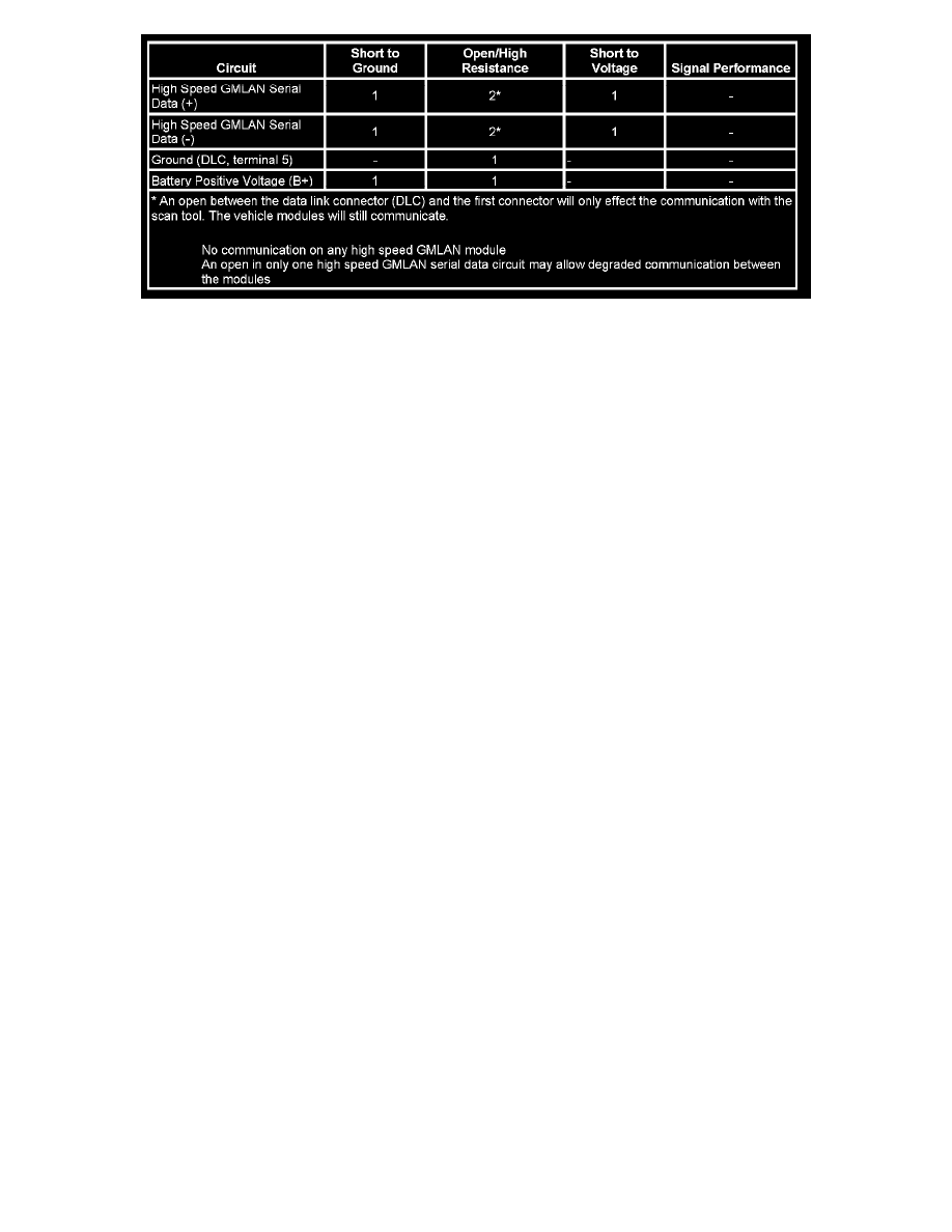
The following conditions may cause a total loss of high speed GMLAN data communication:
-
A short between high speed GMLAN (+) and high speed GMLAN (-) circuits
-
Any of the high speed GMLAN serial data circuits shorted to ground or voltage
-
A module internal malfunction that causes a short to voltage or ground on the high speed GMLAN circuits
Circuit/System Testing
1. Test for less than 1.0 ohm of resistance between the DLC ground circuit terminal 5 and ground.
^
If greater than the specified range, test the ground circuit for open/high resistance.
2. Remove the terminator resistor.
3. Test for 110-130 ohms of resistance between the terminals of the resistor.
^
If not within the specified range, replace the resistor.
4. Ignition OFF, disconnect the harness connector X 3 of the BCM.
5. Ignition ON, test for less than 1 volt between the high speed GMLAN serial data circuit of the DLC terminal 6 and ground, and terminal 14 and
ground.
^
If greater than the specified range, test the serial data circuit for a short to voltage.
6. Test for infinite resistance between the high speed GMLAN serial data circuit of the DLC terminal 6 and ground, and terminal 14 and ground.
^
If less than the specified value, test the serial data circuit for a short to ground.
7. Test for infinite resistance between the high speed GMLAN serial data circuits of the DLC terminal 6 and 14.