
Impala V8-5.3L (2008)
7. Insert one tumbler spring (2) each into the 4 tumbler spring holes.
8. The first tumbler to be loaded will be key cut position number 2. Determine the cut depth at this position and install the corresponding tumbler (3)
into the tumbler slot nearest the front of the cylinder assembly.
9. In the same manner, determine the cut depth and corresponding tumbler and install the 3 remaining tumblers (3) into the tumbler slots located at
key cut positions 4, 6, and 8.
10. Check for correct loading by holding the tumblers (3) in position and fully inserting the matching key into the cylinder assembly (1). The sidebar
(5) should be flush with the outside diameter of the cylinder assembly.
11. Lightly lubricate the tumbler (3) surfaces using the lubrication provided.
12. With the matching key fully inserted into the cylinder assembly (1), install and stake one tumbler retainer (4) into the recessed area on the cylinder.
Be careful not to damage the cylinder assembly in any way while staking the tumbler retainer.
13. Rotate the cylinder assembly (1) to the opposite side and repeat the procedure defined in the previous step.
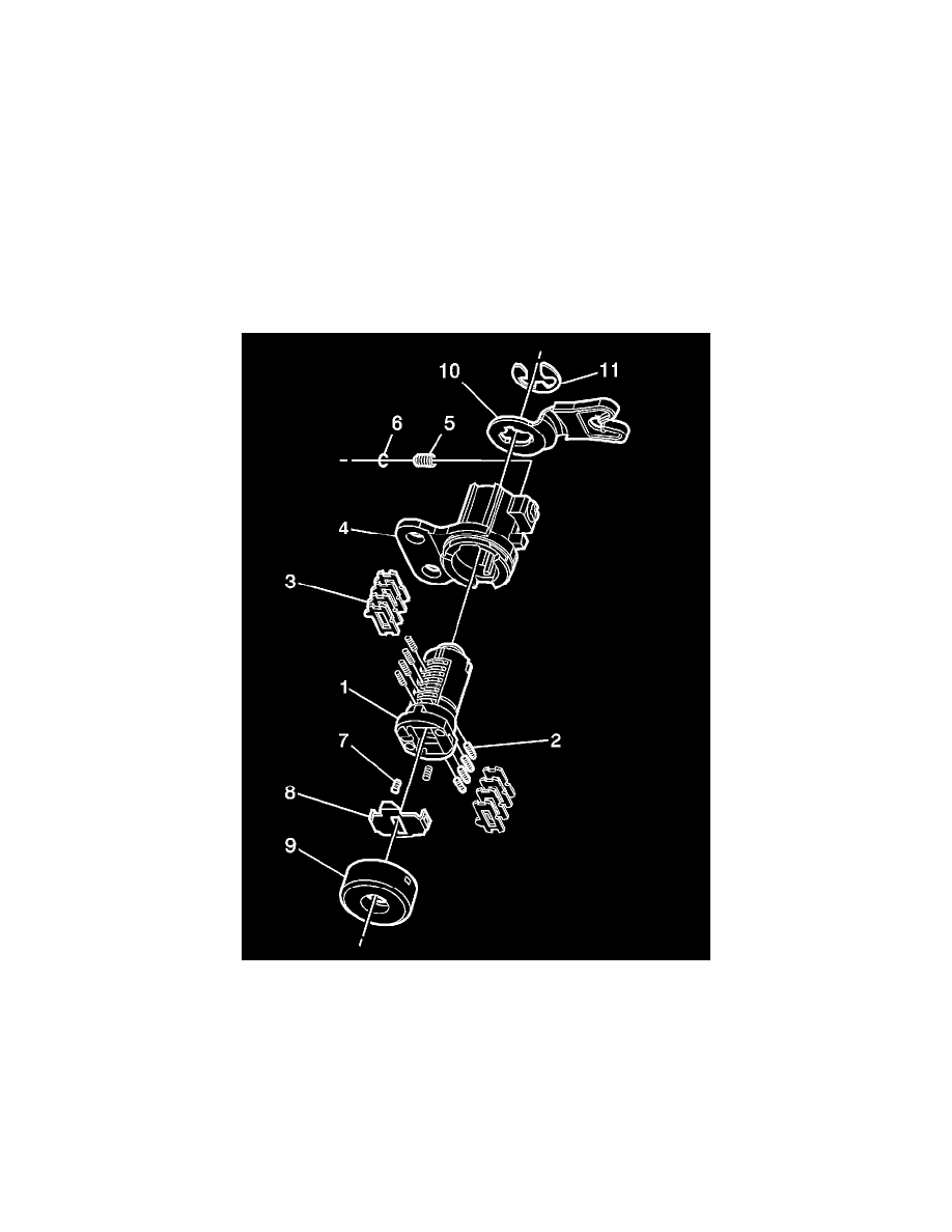
Front Side Door Lock Cylinder
The front side door lock cylinder uses 8 of the 10 key cut positions, 3 through 10 when counting from the key head. The tumbler orientations alternate in
adjacent locations from side to side with 4 on each side.
Important: The front side door lock cylinder tumblers (3) are not self-retaining and must be held in place if the key in not fully inserted
into the lock cylinder or until the cylinder (1) is assembled into the case assembly (4). Left side shown, right side opposite.
1. Hold the uncoded cylinder (1) positioned so the side with the rotational stop lug is facing upward, as shown.
2. Insert one tumbler spring (2) each into the 4 tumbler spring holes.
3. The first tumbler to be loaded will be key cut position 3, the third number in the key code. Determine the cut depth at this position and install the
corresponding tumbler (3) into the tumbler slot nearest the front of the lock cylinder assembly (1), the end where the key is inserted.
4. In the same manner, determine the cut depth and corresponding tumbler and install the 3 remaining tumblers (3) into the tumbler slots located at
key cut positions 5, 7, and 9.
5. Check the correct loading by holding the tumblers (3) in position and fully inserting the matching key into the cylinder (1). All tumblers should be
flush with the outside diameter of the cylinder.
6. Rotate the cylinder (1) so the side with the rotational stop lug is facing downward and then remove the matching key. Remember the tumblers (3)