
K 1500 Truck 4WD V6-4.3L VIN W (1997)
Torsion Bar: Service and Repair
Torsion Bar(s) And Support Assembly Replacement 4 Dr Utility
^
Tool Required:
-
J 36202 Torsion Bar Unloading Tool
-
Or Equivalent
REMOVAL
Remove or disconnect the following:
-
Raise the vehicle and support it with suitable safety stands.
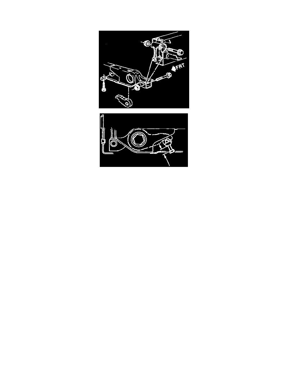
1. Adjustment assemblies on both torsion bars.
a. Mark the adjustment bolt setting.
b. Increase the tension on the adjustment arm using J 36202.
c. Remove the adjustment bolt and retaining plate.
d. Decrease the tension on the adjustment arm using J 36202.
e. Move the tool aside.
f.
Slide the torsion bars forward.
g. Remove the adjustment arms.
2. Nuts and bolts from the torsion bar support crossmember link assembly.
3. Torsion bars.
-
Note the location and the front ends of the torsion bars. There are different bars for the left and right sides.
4. Support crossmember.
5. Link assembly from the support crossmember.
INSTALLATION
CAUTION: Always use the correct fastener in the proper location. When you replace a fastener, use ONLY the exact part number for that
application. The manufacturer will call out those fasteners that require a replacement after removal. The manufacturer will also call out the fasteners
that require thread lockers or thread sealant. UNLESS OTHERWISE SPECIFIED, do not use supplemental coatings (paints, greases, or other
corrosion Inhibitors) on threaded fasteners or fastener joint interfaces. Generally, such coatings adversely affect the fastener torque and joint clamping
force, and may damage the fastener. When you install fasteners, use the correct tightening sequence and specifications. Following these instructions
can help you avoid damage to parts and systems.
Install or connect the following:
1. Link assembly on the support crossmember.
2. Support crossmember assembly to the frame, rearward of the mounting holes.
3. Torsion bars.
-
Make sure the bars are on their respective sides.