
K 30 P/U 4WD V6-262 4.3L (1985)
Intake Manifold: Service and Repair
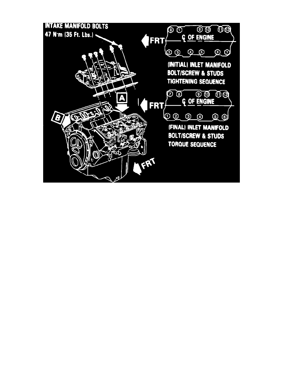
Fig. 10 Intake manifold tightening sequence. V6-262
Series 10---30/1500---3500
1.
Disconnect battery ground cable.
2.
On G models, remove engine cover.
3.
On all models, remove air cleaner, then drain cooling system.
4.
Remove distributor cap and wires, then disconnect ESC connector, if applicable.
5.
Remove distributor.
6.
Disconnect detent and accelerator cables.
7.
If equipped with A/C, remove rear compressor brace.
8.
Remove transmission and engine oil filler tubes from alternator brace.
9.
If equipped with A/C, remove idler pulley.
10.
Remove alternator brace, then on carbureted models, disconnect fuel line from carburetor.
11.
Disconnect all vacuum hoses and electrical connections from carburetor or TBI unit.
12.
Remove AIR hoses and brackets, then disconnect heater hose from intake manifold and remove carburetor.
13.
Remove intake manifold attaching bolts, then the intake manifold.
14.
Reverse procedure to install, using new gaskets and seals. Coat front and rear ridges of cylinder case with a 3/16 inch bead of RTV sealant. Extend
bead 1/2 inch up each cylinder head to retain side gaskets, then seal around all water passages. Torque manifold bolts to specification in sequence
shown in Fig. 10.