
K 3500 Truck 4WD V8-5.7L VIN R (1998)
Electronic Brake Control Module: Service and Repair
REMOVAL PROCEDURE
Important: After installation, calibrate the new Electronic Brake Control Module (EBCM) to the tire size that is appropriate to the vehicle. Refer
to Tire Size Calibration and to Trim Level Calibration portions of "ABS System Description". See: Brakes and Traction Control/Antilock Brakes /
Traction Control Systems/Description and Operation
1. Negative Battery Cable.
CAUTION: Before removing or installing any electrical unit or when a tool or equipment could easily come in contact with "live"
exposed electrical terminals, disconnect the negative battery cable to help prevent personal injury and/or damage to the vehicle or
components. Unless instructed otherwise, the ignition switch must be in the "OFF" or "LOCK" position.
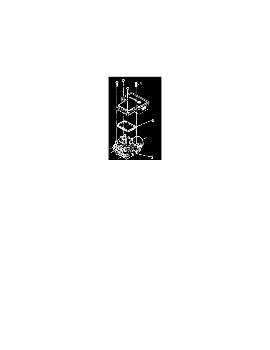
2. Remove the four T-25 Torx screws (1) that fasten the EBCM to the Brake Pressure Modulator Valve (BPMV).
3. Partially remove the EBCM (2) from the BPMV (4) enough to access the electrical connectors. Removal may require a light amount of force.
Important: Do not use a tool to pry the EBCM or the BPMV. Excessive force will damage the EBCM.
4. Disconnect the four electrical connectors from EBCM.
5. Fully remove the EBCM (2) from the BPMV (4).
INSTALLATION PROCEDURE
Important: Do not reuse the old mounting screws. Always install new mounting screws with the new EBCM.
1. Install the new EBCM gasket (3) onto the BPMV (4).
Important: Do not use RTV or any other type of sealant on the EBCM gasket or mating surfaces.
2. Install EBCM (2) on to the BPMV (4).
3. Connect the four electrical connectors to the EBCM.
4. Ensure that the new EBCM gasket (3) is aligned correctly.
5. Install the four new T-25 Torx screws (1) in the EBCM (0).
^
Tighten the four T-25 Torx screws to 5 Nm (39 inch lbs.) in an X-pattern.
NOTICE: Refer to Fastener Notice in Service Precautions.
6. Connect the negative battery cable.
7. Revise the tire calibration using the Scan Tool
8. Return to "ABS Diagnostic System Check".