
Lumina V6-191 3.1L VIN T MFI (1993)
Valve Body Cover
TOOLS REQUIRED
^
J 28467-A Engine Support Fixture
^
J 36462 Engine Support Adapter Leg
REMOVE OR DISCONNECT
1. Air cleaner assembly.
2. Negative battery cable.
3. Left torque strut at engine.
4. Left torque strut bracket.
5. One bolt at top of transaxle mount bracket
6. Install J-28467-A and J-36462 Engine support fixtures, or equivalent.
7. T.V. cable.
8. Raise vehicle and support.
9. Left front tire and wheel assembly.
10. Left lower engine splash shield.
11. Left lower ball joint.
12. Pinch bolt at intermediate steering shaft.
CAUTION: Failure to disconnect the intermediate shaft from the rack and pinion stub shaft can result in damage to the steering gear or
intermediate shaft. Loss of steering control could result.
13. Support right and left sides of frame with jackstands.
14. Right frame to body bolts.
15. Left frame to body bolts, and adjust jackstand to lower left side of frame.
16. Transaxle mount and mount support. Refer to "Transaxle Mount".
17. Bolts holding engine wiring harness to transaxle case.
18. Transaxle oil cooler lines at transaxle.
19. Transaxle mount bracket. Refer to "Transaxle Mount".
20. Position drain pan under transaxle.
21. Valve body cover pan and gasket.
INSTALL OR CONNECT
1. Valve body cover pan and gasket.
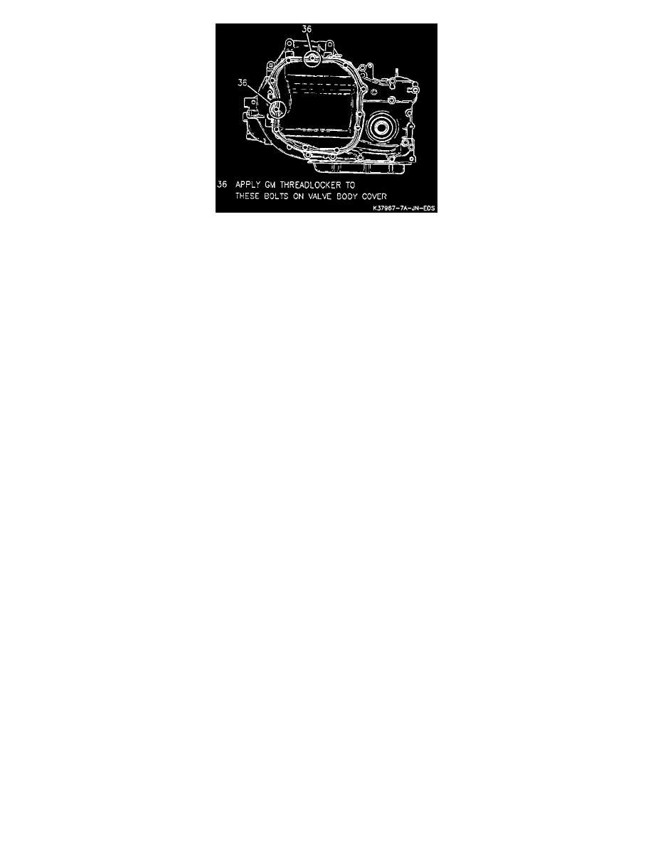
NOTE: It is necessary to use GM thread locker (P/N 12345382) or equivalent non-locking sealant to reduce the potential for fluid leaks on the
indicated bolts in the above figure.
2. Valve body cover bolts and channel plate flange nuts.
3. Torque bolts and nuts to 11 Nm (97 in lb).
4. Transaxle mount bracket. Refer to "Transaxle Support Assembly (Bracket)".
5. Transaxle oil cooler lines at transaxle.
6. Engine wiring harness to transaxle case.
7. Transaxle mount and mount support. Refer to "Transaxle Mount".
8. Raise left side of frame and install new frame to body bolts.
9. Pinch bolt at intermediate steering shaft.
CAUTION: When installing the intermediate shaft make sure the shaft is seated prior to pinch bolt installation. If the pinch bolt is inserted