
Lumina APV V6-191 3.1L VIN D TBI (1995)
Engine Control Module: Description and Operation
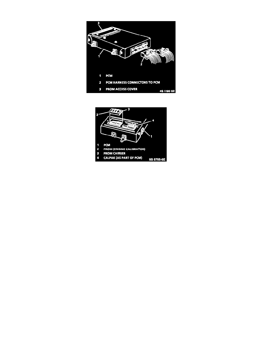
Powertrain Control Module
PROM Location
GENERAL DESCRIPTION
NOTE: To prevent possible Electrostatic Discharge damage to the Powertrain Control Module (PCM), Do not touch the connector pins or soldered
components on the circuit board.
The PCM, located under the instrument panel, is the control center of the fuel injection system. It constantly looks at the information from various
sensors and controls the systems that affect vehicle performance. The PCM performs the diagnostic function of the system. It can recognize
operational problems, alert the driver through the MIL (Service Engine Soon), and store a DTC or DTC(s) which identify the problem areas to aid
the technician in making repairs. For service, the PCM has two parts: a controller (the PCM without the PROM), and a separate calibrator (PROM).
Prom
NOTE: To prevent possible Electrostatic Discharge damage to the PROM or PCM, Do Not touch the component leads, and Do Not remove
integrated circuit from carrier.
To allow one model of PCM to be used for many different vehicles, a device called PROM (Programmable Read Only Memory) is used. The
PROM is located inside the PCM and contains information for specific vehicle applications. While one PCM part number can be used by many
vehicle lines, a PROM is very specific and must be used for the right vehicle. For this reason, it is very important to check the latest parts book and
Service Bulletin information for the correct part number when replacing a PROM.
A PCM used for service (called a controller) comes without a PROM. The PROM from the old PCM must be carefully removed and installed in
the new PCM.
PCM FUNCTION
The PCM supplies either 5 or 12 volts to power various sensors or switches. This is done through resistances in the PCM which are so high in value
that a test light will not light when connected to the circuit. In some cases, even an ordinary shop voltmeter will not give an accurate reading because
its resistance is too low. Therefore, a 10 megohm input impedance digital voltmeter is required to assure accurate voltage readings.
The PCM controls output circuits such as the injector, Idle Air Control (IAC), cooling fan relay, etc. by controlling the ground circuit through
transistors in the PCM.
The PCM supplies either 5 or 12 volts to power various sensors or switches. This is done through resistances in the PCM which are so high in value