
Malibu L4-2.2L VIN F (2005)
IMPORTANT: On connectors with more than one terminal the service loop may not be large enough to remove the terminal and crimp on a new
one. If the terminal wire does not have a large enough service loop for removal, cut the wire 5 cm (2 in) behind the connector before removal.
TERMINAL REPAIR
1. If the wire needed to be cut in order to remove the terminal, gently push a small length of the same size wire through the back of the connector
cavity until there is enough wire exposed in order to crimp on a new terminal. If the wire was not cut, cut the existing wire as close to the old
terminal as possible.
2. Strip 5 mm (3/16 in) of insulation from the wire.
3. Crimp a new terminal to the wire.
4. Solder the crimp with rosin core solder.
TERMINAL INSTALLATION
1. Align the terminal and pull the wire from the back of the connector in order to seat the terminal.
2. If necessary, cut the new wire to proper length and splice with existing circuit. Refer to Splicing Copper Wire Using Splice Sleeves.
3. If the connector is outside of the passenger compartment, apply dielectric grease to the connector.
4. Install the TPA, CPA and/or the secondary locks.
Micro .64 Connectors
MICRO.64 CONNECTORS
TOOLS REQUIRED
J 38125 Terminal Repair Kit
REMOVAL PROCEDURE
Follow the steps below in order to remove terminals from Micro 64 connectors.
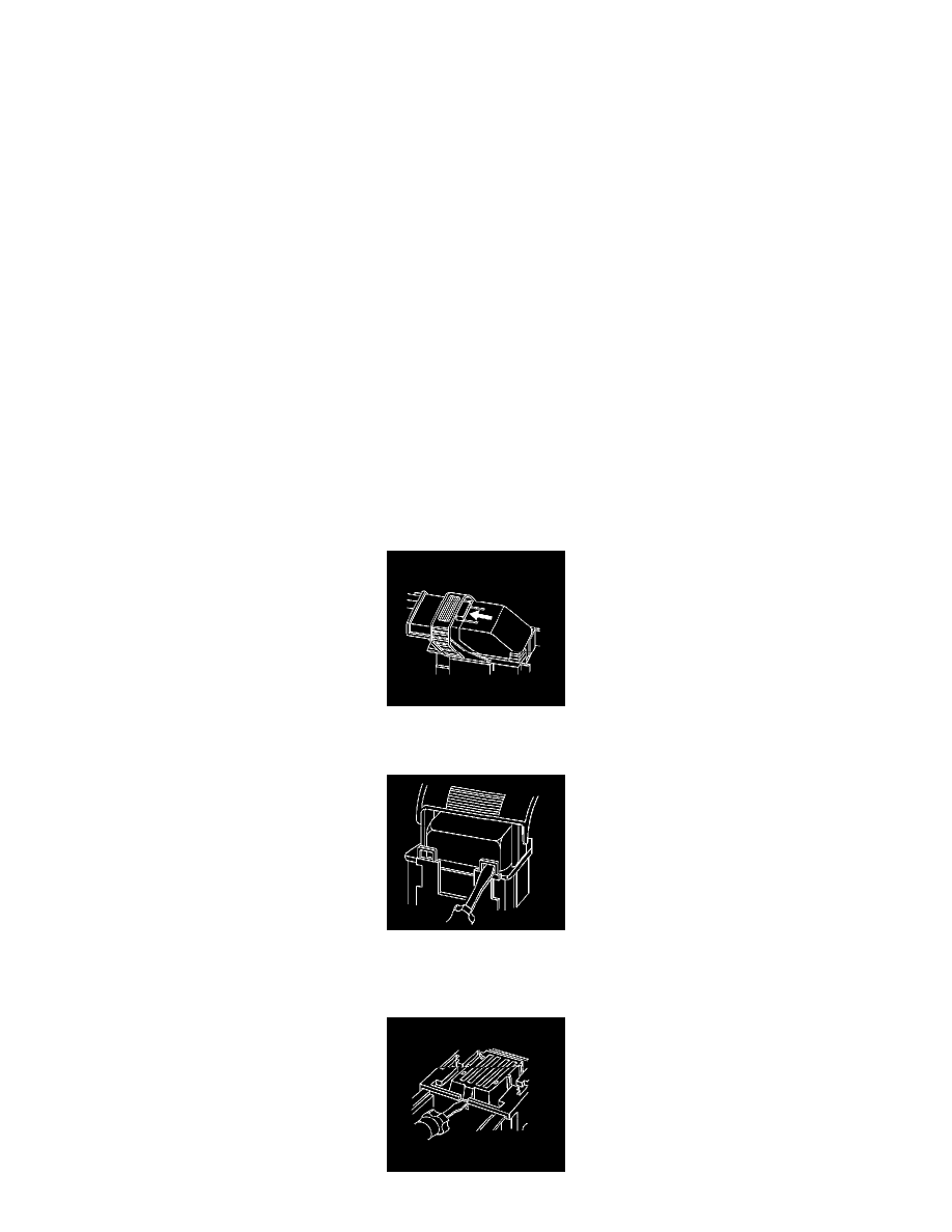
1. Locate the lever lock on the wire dress cover. While depressing the lock, pull the lever over and past the lock.
2. Disconnect the connector from the component.
3. Locate the dress cover locking tabs at the front of the connector. Using a small flat-blade tool push down on one of the locking tabs and pull the
cover up until the dress cover releases. Repeat this procedure for the other locking tab.
4. Once the front 2 locks are unlocked, lift the front of the dress cover and pull it forward.