
Malibu L4-2.4L (2010)
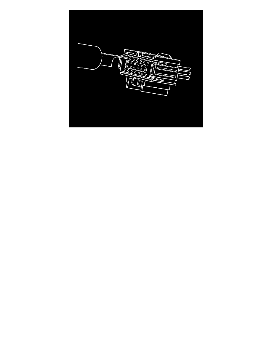
7. View of the male half of the connector with female terminals.
8. While holding the removal tool in place, gently pull the wire out of the back of the connector. Always remember never use force when pulling a
terminal out of a connector.
Repair Procedure
Use the appropriate terminal and follow the instructions in the J-38125.
Location of the terminal in the repair tray and the proper crimp tool can be found in the appropriate connector end view.
Repairing Connector Terminals
Repairing Connector Terminals
Special Tools
J-38125 Terminal Repair Kit
Use the following repair procedures in order to repair the following:
*
Push to Seat terminals
*
Pull to Seat terminals
Some terminals do not require all of the steps shown. Skip the steps that do not apply for your terminal repair. The J-38125 contains further information.
1. Cut off the terminal between the core and the insulation crimp. Minimize any wire loss.
For cable seal terminals, remove the seal.
2. Apply the correct cable seal per gauge size of the wire, if used.
Slide the seal back along the wire in order to enable insulation removal.
3. Remove the insulation.
4. For sealed terminals only, align the seal with the end of the cable insulation.
5. Position the strip in the terminal.
For sealed terminals, position the strip and seal in the terminal.
6. Hand crimp the core wings.
7. Hand crimp the insulation wings.
For sealed terminals, hand crimp the insulation wings around the seal and the cable.
8. Solder all of the hand crimp terminals excepting Micro-Pack 100.64 size. Soldering Micro-Pack 100 World terminals may damage the terminal.
Sumitomo Connectors