
Malibu L4-2.4L (2010)
Condenser Fan: All Technical Service Bulletins
A/C - Poor Cooling Performance/Condenser Fan Fuse Blown
TECHNICAL
Bulletin No.: 09-01-38-005
Date: October 09, 2009
Subject: Poor A/C Performance, Cooling Fan Fuse Blown (Install Revised Fuse And Wiring)
Models:
2008-2010 Chevrolet Malibu
2006-2010 Pontiac G6
2007-2010 Saturn AURA
All with RPO LY7, LZ4, LZ9 or LZE V6 Engine
Condition
Some customers may comment on poor A/C cooling performance.
Technicians may find that the cooling fan fuse is blown.
Cause
High cooling fan start up loads may cause the 30-amp cooling fan fuse, located in the underhood fuse block, to blow. The lack of air flow through the
A/C condenser, caused by the inoperative high-speed cooling fan, may affect the condenser's ability to dissipate heat.
Correction
Use the following procedure to install a heavier gauge power feed wire from the underhood fuse block to the cooling fan. After the wiring update is
completed, replace the 30-amp cooling fan fuse in the underhood fuse block with a 40-amp fuse.
1. Disconnect and remove the battery. Refer to Battery Replacement in SI.
2. Remove the windshield washer fill tube. Refer to Windshield Washer Solvent Container Filler Tube Replacement in SI.
3. Disconnect the underhood fuse block from it's mounting base. Refer to Underhood Electrical Center or Junction Block Replacement in SI. It is
only necessary to raise the fuse block enough to access the harness connectors. Do not remove the complete assembly from the vehicle.
4. Locate the engine wiring harness junction block assembly (X1) on the back (underside) of the underhood fuse block and disconnect it from the
underhood fuse block. Refer to Electrical Center Identification Views, Fuse Block Underhood Bottom View in SI.
5. Find pin A2, Circuit 532, cooling fan motor supply voltage. Refer to Electrical Center Identification Views, Fuse Block-Underhood X1 in SI.
6. Remove the harness back cover. Remove the TPA (terminal position assurance) clip and remove connector A2 from the junction block. Cut the
terminal off and tape the wire end with electrical tape.
7. Remove the air cleaner outlet duct. Refer to Air Cleaner Outlet Duct Replacement in SI.
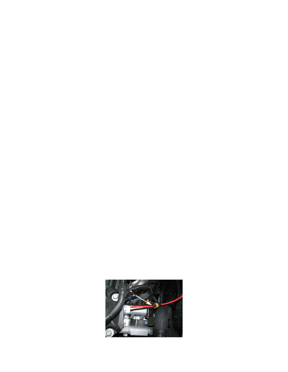
8. Locate the electrical connector to the right cooling fan and disconnect the wiring connector from the fan.
9. Disengage pin B, wire 3 GY, circuit 532, cooling fan motor supply voltage, from the connector housing (pull to seat terminal). Cut the terminal off
of the wire and remove the wire from the connector housing.
10. Tape the end of the wire with electrical tape.
11. Prepare a 1.82 m (6 ft) section of automotive grade 5.0 mm (10 GA) wire and an equal length of 6 mm (1/4 in) flexible plastic conduit, GM P/N
12051375.
12. Run the new wire through the fan wire connector housing as shown.
13. Obtain the terminals listed below from the J 38125 Terminal Repair Kit.
14. Strip the wire insulation as required and install the terminal, GM P/N 12033997, on the wire. Secure the wire and terminal into the fan wire