
Metro L3-061 1.0L VIN 6 TBI (1998)
Alignment: Service and Repair
Rear Wheel Alignment
MEASURING REAR ALIGNMENT ANGLES
Important:
^
Install the alignment equipment following the equipment manufacturer's instructions. Measure the alignment angles and record the readings.
^
Jounce the front and rear bumpers three times: to normalize the suspension prior to measuring the angles.
^
If the caster angles are riot within the specified range, inspect for damaged suspension and steering components and replace parts as necessary.
REAR CAMBER ADJUSTMENT
Should camber be found out of specification upon inspection (camber -1.0 to 1.0°), locate its cause first. If the cause lies in damaged, loose, bent,
dented or worn suspension parts, those parts should be replaced. Refer to REAR SUSPENSION. If the problem lies in the body, repair it to attain
specifications. Refer to ALIGNMENT CHECKING in UNDERBODY. to prevent the possible incorrect reading of caster, the vehicle front end must
be moved up and down a few times bounced) before inspection. Rear camber cannot be adjusted on this vehicle.
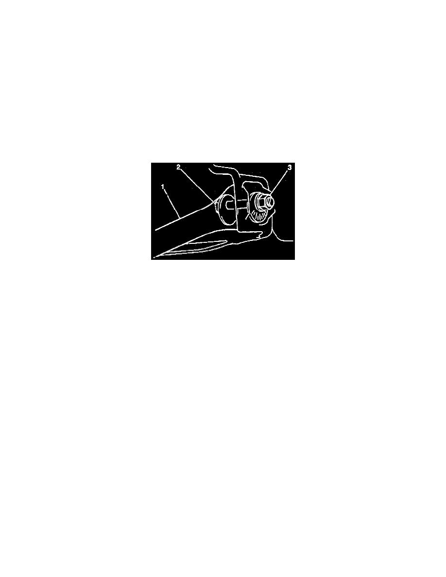
REAR TOE ADJUSTMENT
1. Adjust the rear toe by loosening/tightening both body-side (cam) control rod nuts (3) and bolts (2).
2. Loosen the right and left body-side control rod nuts (3).
3. Loosen the right and left body-side control rod bolts (cam bolts) (2) by the same amount.
4. Set the rear total toe to 0.3 to 0.6°.
NOTICE: Always use the correct fastener in the proper location. When you replace a fastener, use ONLY the exact part number for that
application. The manufacturer will call out those fasteners that require a replacement after removal. The manufacturer will also call out the
fasteners that require thread lockers or thread sealant. UNLESS OTHERWISE SPECIFIED, do not use supplemental coatings (paints, greases, or
other corrosion inhibitors) on threaded fasteners or fastener joint interfaces. Generally, such coatings adversely affect the fastener torque and joint
clamping force, and may damage the fastener. When you install fasteners, use the correct tightening sequence and specifications. Following these
instructions can help you avoid damage to parts and systems.
Important: Hold the control rod bolt with a wrench to prevent it from fuming while tightening the control rod nuts.
5. Install the left and right body-side control rod nuts.
Tighten
Tighten the left and right body-side control rod nuts to 80 Nm (59 ft. lbs.).