
Prizm L4-108 1.8L DOHC VIN 8 MFI (1998)
^
Insert the Weather Pack(R) terminal removal tool into the front (mating end) of the connector cavity until it rests on the cavity shoulder (1).
^
Gently pull on the wire to remove the terminal through the back of the connector (2).
IMPORTANT: Never use force to remove a terminal from a connector.
^
Inspect the terminal and connector for damage. Repair as necessary. Refer to Repairing Connector Terminals.
^
Reform the lock tang (2) and reset terminal in connector body.
^
Close secondary locks and join connector halves.
^
Verify that circuit is complete and working satisfactorily.
^
Perform system check.
Flat Wire Repairs
NOTE: The flat wire within the flex wiring harness is not serviceable. If an open or short exists within the flex wiring harness the complete harness
must be replaced.
HO2S Wiring Repairs
NOTE: Do not solder repairs under any circumstances as this could result in the air reference being obstructed.
If the heated oxygen sensor pigtail wiring, connector, or terminal is damaged the entire oxygen sensor assembly must be replaced. Do not attempt to
repair the wiring, connector, or terminals. In order for the sensor to function properly it must have a clean air reference. This clean air reference is
obtained by way of the oxygen sensor signal and heater wires. Any attempt to repair the wires, connectors or terminals could result in the obstruction of
the air reference and degrade oxygen sensor performance.
The following guidelines should be used when servicing the heated oxygen sensor:
^
Do not apply contact cleaner or other materials to the sensor or vehicle harness connectors. These materials may get into the sensor, causing poor
performance. Also, the sensor pigtail and harness wires must not be damaged in such a way that the wires inside are exposed. This could provide a
path for foreign materials to enter the sensor and cause performance problems.
^
Neither the sensor nor vehicle lead wires should be bent sharply or kinked. Sharp bends, kinks, etc., could block the reference air path through the
lead wire.
^
Do not remove or defeat the oxygen sensor ground wire (where applicable). Vehicles that utilize the ground wire sensor may rely on this ground as
the only ground contact to the sensor. Removal of the ground wire will also cause poor engine performance.
^
To prevent damage due to water intrusion, be sure that the peripheral seal remains intact on the vehicle harness connector.
The engine harness may be repaired using the J 38125-B.
Repairing Damaged Wire Insulation
If the conductive portion of the wire is not damaged, locate the problem and apply tape around the wire. If the damage is more extensive, replace the
faulty segment of the wire. Refer to Splicing Copper Wire Using Splice Clips and follow the instruction to repair the wire. See: Wire Repair
Procedures/Typical Electrical Repair Procedures/Splicing Copper Wire Using Splice Clips
SIR Wiring Repairs
J 38125-B Terminal Repair Kit
IMPORTANT:
^
Refer to Wiring Repairs in order to determine the correct wire size for the circuit being repaired. Using the correct wire size ensures that circuit
integrity is not compromised. See: Diagrams/Diagnostic Aids/Wire Repair Procedures
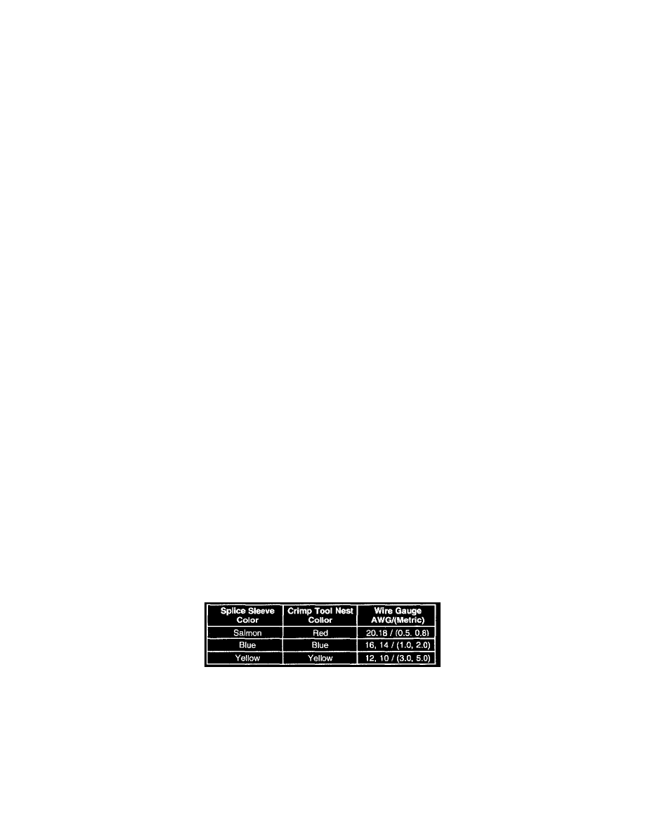
Crimp And Seal Splice Table
If any wire except the pigtail is damaged, repair the wire by splicing in a new section of wire of the same gauge size (0.5 mm, 0.8 mm, 1.0 mm,
etc.). Use the sealed splices and splice crimping tool from the J 38125-B. Use the following wiring repair procedures to ensure the integrity of the
sealed splice.
^
Perform the following procedures in the listed order. Repeat the procedure if any wire strands are damaged.
1. Open the harness by removing any tape. To avoid wire insulation damage use a sewing seam ripper (available from sewing supply stores) to cut
open the harness.