
Prizm L4-108 1.8L DOHC VIN 8 MFI (1998)
Fuses
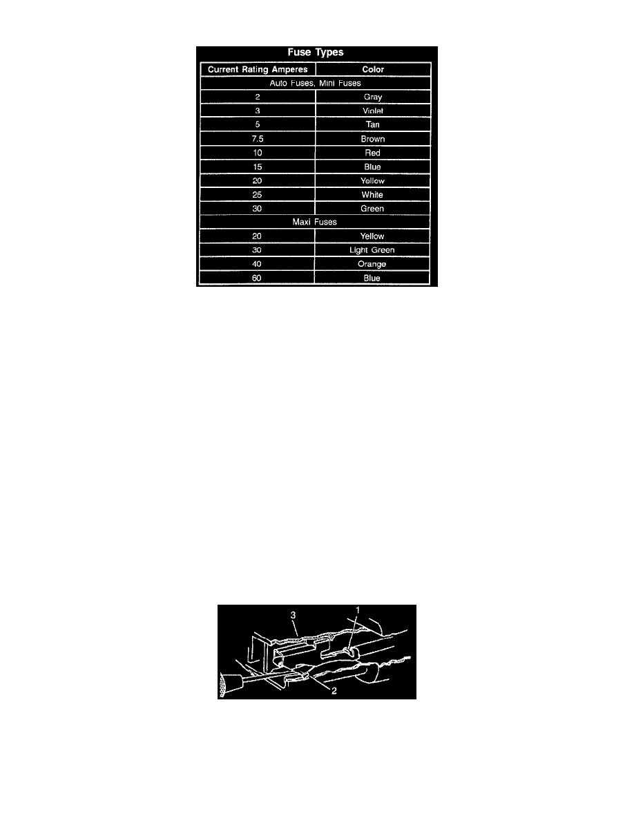
Fuse Types
The fuse is the most common method of an automotive wiring circuit protection. Whenever there is an excessive amount of current flowing through a
circuit the fusible element will melt and create an open or incomplete circuit. Fuses are an one time protection device and must be replaced each time the
circuit is overloaded. To determine if a fuse is open, remove the suspected fuse and examine the element in the fuse for an open (break). If not broken,
also check for continuity using a J 39200 DMM or a continuity tester. If the element is open or continuity is suspect, replace the fuse with one of equal
current rating.
Fusible Links
Fusible link is wire designed to melt and break continuity when excessive current is applied. It is often located between or near the battery and starter or
electrical center. Use a continuity tester or a J 39200 DMM at each end of the wire containing the fusible link in order to determine if it is broken. If
broken, it must be replaced with fusible link of the same gage size.
Repairing a Fusible Link
IMPORTANT: Fusible links cut longer than 225 mm (approx. 9 inches) will not provide sufficient overload protection.
Refer to Splicing Copper Wire Using Splice Clips. See: Wire Repair Procedures/Typical Electrical Repair Procedures/Splicing Copper Wire
Using Splice Clips
Connector Position Assurance Locks
The Connector Position Assurance (CPA) is a small plastic insert that fits through the locking tabs of all the SIR system electrical connectors. The CPA
ensures that the connector halves cannot vibrate apart. You must have the CPA in place in order to ensure good contact between the SIR mating
terminals.
Pull-to-Seat Connectors
TERMINAL REMOVAL
Push To Seat Connector: Terminal Removal
Follow the steps below in order to repair pull-to-seat connectors.
1. Remove the Terminal Position Assurance (TPA) device, the Connector Position Assurance (CPA) device, and/or the secondary lock.
2. Separate the connector halves.
3. Using the proper pick or removal tool (4) insert into the front of the connector body.
4. Grasp the wire at the back of the connector body and gently pull the terminal (1) from the connector body (3).