
Prizm L4-108 1.8L DOHC VIN 8 MFI (1998)
the DMM.
7. When the DMM displays low or no resistance, there is a short to ground in the wiring near that point.
WITH A DMM SET TO VOLTAGE FUNCTION
1. Remove the open fuse.
2. Disconnect the load.
3. Connect a DMM across the fuse terminals (be sure that the fuse is powered).
4. Beginning near the fuse block, wiggle the harness from side to side. Continue this at convenient points (about 6 inches apart) while watching
the DMM.
5. When the DMM displays voltage, there is a short to ground in the wiring near that point.
WITH A TEST LIGHT
1. Remove the open fuse.
2. Disconnect the load.
3. Connect a test light across the fuse terminals (be sure that the fuse is powered).
4. Beginning near the fuse block, wiggle the harness from side to side. Continue this at convenient points (about 6 inches apart) while watching
the test light.
5. When the test light glows there is a short to ground in the wiring near that point.
FUSE POWERING SEVERAL LOADS
1. Review the system schematic and locate the fuse that is open.
2. Open the first connector or switch leading from the fuse to each load.
3. Connect a DMM across the fuse terminals (be sure that the fuse is powered).
^
When the DMM displays voltage the short is in the wiring leading to the first connector or switch.
^
If the DMM does not display voltage refer to the next step.
4. Close each connector or switch until the DMM displays voltage in order to find which circuit has the short.
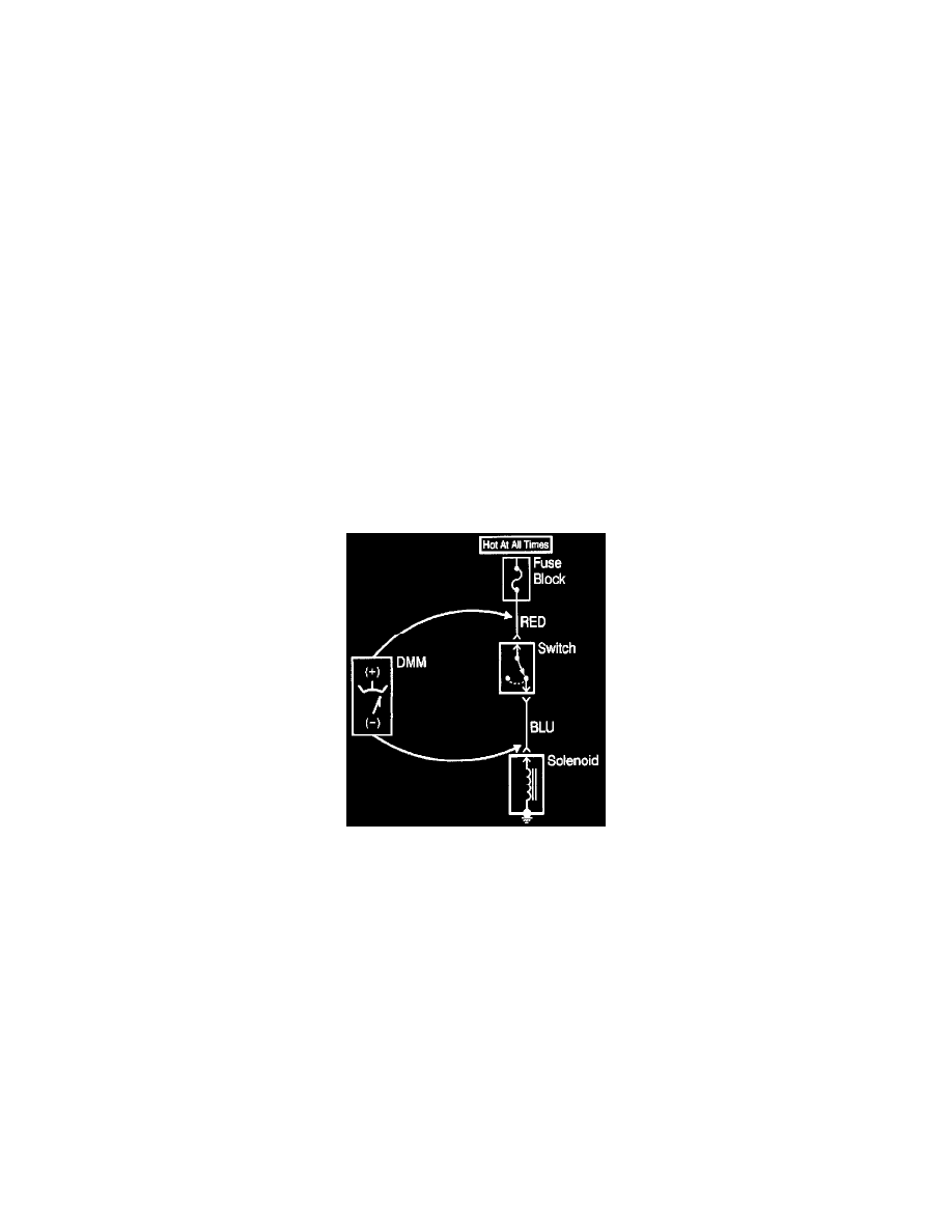
Testing For Voltage
Testing For Voltage
This test checks for voltage along a wire through a connection or switch.
1. Apply power to the circuit.
2. Place meter leads in the COM (black) and V ohm inputs.
3. Place the rotary switch (meter) in the V (AC) or V (DC) position.
4. Connect the positive lead of a DMM to the end of the wire, (or to one side of the connection or switch) which is closer to the battery.
5. Connect the negative lead to the other end of the wire (or the other side of the connection or switch).
6. Operate the circuit.
Testing For Voltage Drop