
Prizm L4-108 1.8L DOHC VIN 8 MFI (1998)
6. To repair the terminal, refer to Terminal Repair.
Terminal Repair
1. Slip the cable seal away from the terminal.
2. Cut the wire as close to the terminal as possible.
3. Slip a new cable seal onto the wire.
4. Strip 5 mm (3/16 in) of insulation from the wire
5. Crimp a new terminal to the wire.
6. Solder the crimp with rosin core solder.
7. Slide the cable seal toward the terminal.
8. Crimp the cable seal and the insulation.
9. If the connector is outside of the passenger compartment, apply grease to the connector.
Reinstalling Terminal
1. In order to reuse a terminal or lead assembly. Refer to Wiring Repairs. See: Wire Repair Procedures/Circuit Protection Devices
2. Ensure that the cable seal is kept on the terminal side of the splice.
3. Insert the lead from the back until it catches.
4. Install the TPA, CPA and/or the secondary locks.
Repairing Connector Terminals
The following repair procedures can be used to repair Push to Seat, Pull to Seat or Weather Pack(R) terminals. Some terminals do not require all steps
shown. Skip those that do not apply for your immediate terminal repair. The Terminal Repair Kit (J 38125-A) contains further information.
1. Cut off terminal between core and insulation crimp (minimize wire loss) and remove seal for Weather Pack(R) terminals.
2. Apply correct seal per gauge size of wire and slide back along wire to enable insulation removal (Weather Pack(R) terminals only).
3. Remove Insulation.
4. Align seal with end of cable insulation. (Weather Pack« terminals only).
5. Position strip (and seal for Weather Pack(R)) in terminal.
6. Hand crimp core wings.
7. Hand crimp insulation wings (non Weather Pack(R)). Hand crimp insulation wings around seal and cable (Weather Pack(R)).
8. Solder all hand crimp terminals.
Terminal Position Assurance Locks
The Terminal Position Assurance (TPA) insert resembles the plastic combs used in the control module connectors. The TPA keeps the terminal securely
seated in the connector body. Do not remove the TPA from the connector body unless you remove a terminal for replacement.
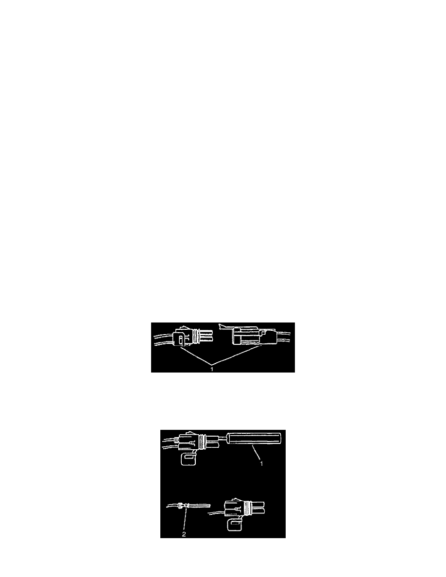
Weather Pack Connectors
The following is the proper procedure for the repair of Weather Pack(R) Connectors.
Weather Pack Connectors
^
Separate the connector halves (1)
^
Open the secondary lock. A secondary lock aids in terminal retention and is usually molded to the connector (1).
^
Grasp the wire and push the terminal to the forward most position. Hold the wire in this position.
Weather Pack Connectors