
Prizm L4-108 1.8L DOHC VIN 8 MFI (1998)
circuit should operate, read the schematic again, this time keeping in mind what has been learned by operating the circuit. Since both the low beam
headlamps operate, ensure that the following components are operating properly.
^
The headlamp Switch.
^
The YEL wire.
^
Low contacts of the Headlamp Dimmer Switch.
^
C100 terminal 1E.
^
The TAN wires.
^
Grounds G105 and G109. Refer to Strategy Based Diagnostic Flow.
Perform the System Check
The system check indicates that the low beam headlamps operate when the high beam switch is in high. Also, the high beam indicator illuminates
but neither high beam headlamp operates. Refer to Strategy Based Diagnostic Flow.
Check for Bulletins
Utilizing a combination of Techline tools and the information accumulated from the Preliminary Checks, check for bulletins.
Isolate the Root Cause
At this point analyze and (diagnose the problem), and develop text. Since the high beam indicator illuminated when the headlamp dimmer switch
was in the high position, the high contacts of the headlamp dimmer switch and the LT GRN wire between the headlamp dimmer switch and C100
are good.
At this point, it is extremely unlikely that the high beam filaments in the RH headlamp are both open or that both headlamp connections are bad.
The cause must be a bad connection at C100 or an open in the LT GRN wire between C100 and the RH headlamp.
Repair and Verify Fix
From isolating the root cause, basically the problem has been diagnosed. Using the Component Location Table and the corresponding figure,
quickly find C100 and the LT GRN wire, locate the exact trouble point and make the repair.
Check the thoroughness of the repair by performing a final system check on the headlamp circuit. This of course means making sure that both high
beams, both low beams, and the high beam indicator are working.
Testing For Continuity
WITH A DMM
Continuity tests work well for detecting intermittent shorts to ground and can be performed by setting the DMM to ohms, then pressing the PEAK
MIN MAX button. An audible tone is heard whenever the DMM detects continuity for at least 1 millisecond. This test checks for continuity along
a wire, through a connection or switch.
1. Remove the negative battery cable.
2. Place the leads of the DMM in COM (black) and V/ohms (red) inputs.
3. Set the rotary dial of the DMM to ohms.
4. Press the PEAK MIN MAX button.
5. Connect one lead of the DMM to one end of the circuit to test.
6. Connect the other lead to the other end of the circuit.
7. If the DMM displays low or no resistance and a tone is heard the circuit being tested has good continuity.
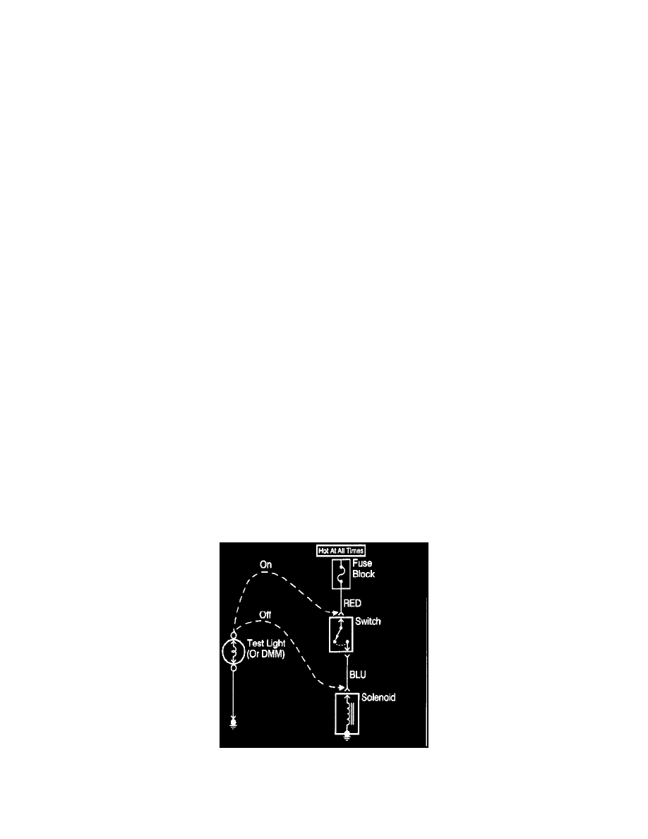
Testing For Continuity
WITH A TEST LIGHT
This test checks for continuity along a wire, through a connection or switch.