
S10/T10 Blazer 4WD V6-4.3L VIN W (1997)
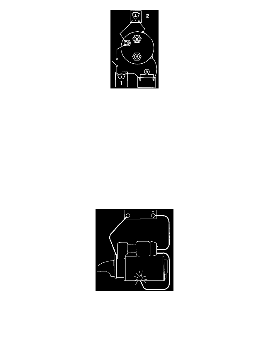
Solenoid Test Connections
NOTE: To prevent overheating of the solenoid pull-in winding, do not leave the winding energized for more than 15 seconds. The current draw will
decrease as the winding temperature increases.
20. Inspect the hold-in winding and the pull-in winding.
Important: Before testing, the solenoid must be removed from the starter motor, or the field lead must be removed from the terminal on the
solenoid.
21. In order to test both windings, perform the following procedure:
21.1.
Connect an ammeter in series with a 12 V battery positive terminal, and the switch (S) terminal on the starter solenoid.
21.2.
Connect a digital multimeter J 39200 to the (S) terminal on the starter solenoid and to the negative battery terminal.
21.3.
Connect the carbon pile (variable resistance) across the battery.
21.4.
Ground the solenoid motor (M) terminal.
21.5.
Adjust the voltage to 10 V and observe the ammeter reading.
21.6.
The reading should be between 60-85 amperes.
^ A higher ammeter reading means that the winding is shorted or grounded.
-
A lower ammeter reading means that there is excessive resistance in the winding.
21.7.
The winding resistance can be read directly. This is done with a digital multimeter J 39200 which measures in tenths of an ohm.
21.8.
Coil resistance is determined by dividing the voltage by the amperes (voltage/amperes).
Starter Pinion Clearance Check
Starter Pinion Clearance Check
The pinion clearance should be checked after reassembly of the starter motor. The pinion clearance cannot be adjusted. Improper clearance is an
indication of worn parts. In order to check the pinion clearance, perform the following procedure:
1. Disconnect the starter motor field connector from the solenoid "M" terminal.
2. Insulate the starter motor field connector carefully.
3. Connect a 12 V battery from the solenoid switch terminal to the solenoid frame.
4. Momentarily flash a jumper lead from the solenoid motor terminal to the solenoid frame. This will shift the pinion into the cranking position. The