
S10/T10 P/U 2WD V6-262 4.3L (1988)
Valve Clearance: Adjustments
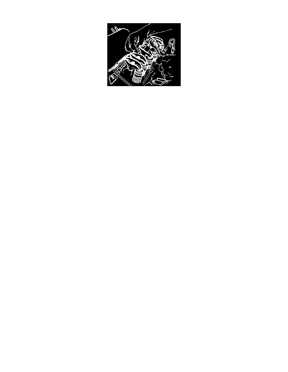
Fig. 14 Valve Adjustment
1.
Remove rocker arm covers as described under COMPONENT REPLACEMENT AND REPAIR PROCEDURES/ROCKER ARM &
PUSHRODS.
2.
Crank engine until mark on torsional damper is aligned with ``0'' mark on timing tab and engine is in No. one cylinder firing position. Ensure
engine is in No. 1 firing position by placing fingers on rocker arms of No. 1 cylinder as timing mark approaches ``0'' mark. If rocker arms are not
moving engine is at the No. 1 firing position. If rocker arms are moving, engine is in the No. 4 firing position and should be rotated one revolution
to the No. 1 position.
3.
Adjust the following valves with the engine in the No. 1 firing position: exhaust 1, 5 and 6; intake 1, 2 and 3. Adjust valves by backing off nut
until lash is felt at the pushrod, then tightening nut until all lash is removed. This can be determined by rotating pushrod while tightening nut. Fig.
14. When all lash is removed, tighten nut one full turn to center pushrod in lifter plunger.
4.
Crank engine one full revolution until mark on torsional damper and ``0'' mark on timing tab are aligned. This is the No. 4 cylinder firing position.
Adjust the following valves: exhaust 2, 3 and 4; intake 4, 5 and 6.
5.
Install valve covers and related components.