
S10/T10 P/U 2WD V6-262 4.3L (1988)
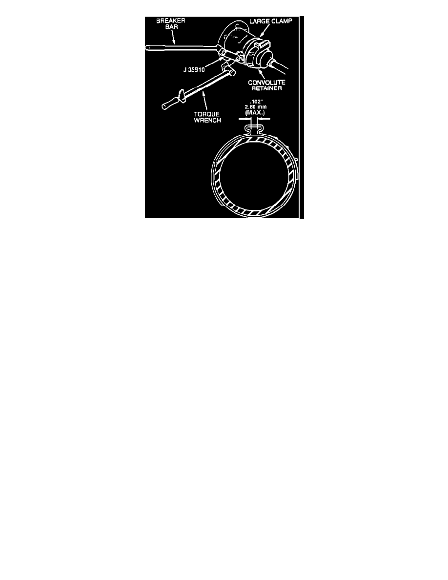
Figure 15 - Large Retaining Clamp Installation
13.
Secure the large metal clamp and seal to the housing with tool J35910, breaker bar and torque wrench. Torque the large clamp to 176 N-m (130
lbs.ft.). Check clamp ear gap dimension (Figure 15).
Halfshaft Installation:
1.
Prior to halfshaft installation, cover shock mounting bracket, lower control arm ball stud, and all other sharp edges with shop towels so that the
seal is not damaged during assembly.
2.
Remove convolute retainer.
3.
Insert and draw up outer C/V joint splined shank into knuckle hub; then secure inboard C/V joint flange to companion flange with bolts (do not
tighten). Install hub nut washer and nut. Seat shank splines in hub.
4.
Connect the upper ball joint to the steering knuckle.
5.
Attach the stud nut and torque 83 N-m (61 lbs.ft.).
6.
Install new cotter pin.
7.
Lubricate the upper ball joint until grease appears at the seal.
8.
Remove floor jack or stand from beneath lower control arm, if used.
9.
Connect the shock absorber to the lower shock mounting bracket.
10.
Attach the shock mounting bolt and nut. Torque the nut and bolt to 73 N-m (54 lbs.ft.).
11.
Attach outer tie rod to steering knuckle.
12.
Install tie rod nut and torque to 47 N-m (35 lbs.ft.).
Important:
Advance the nut to align the nut slot with the cotter pin hole. Never back the nut off to align the cotter pin hole.
13.
Install new cotter pin and spread the ends to secure.
14.
Attach the brake line support bracket to the upper control arm. Torque to 17 N-m (13 lbs.ft.).
Important:
Make sure that the brake hose is not twisted or kinked or damage to the hose could result.