
S10/T10 P/U 2WD V6-4.3L VIN W (1997)
Connecting Rod: Service and Repair
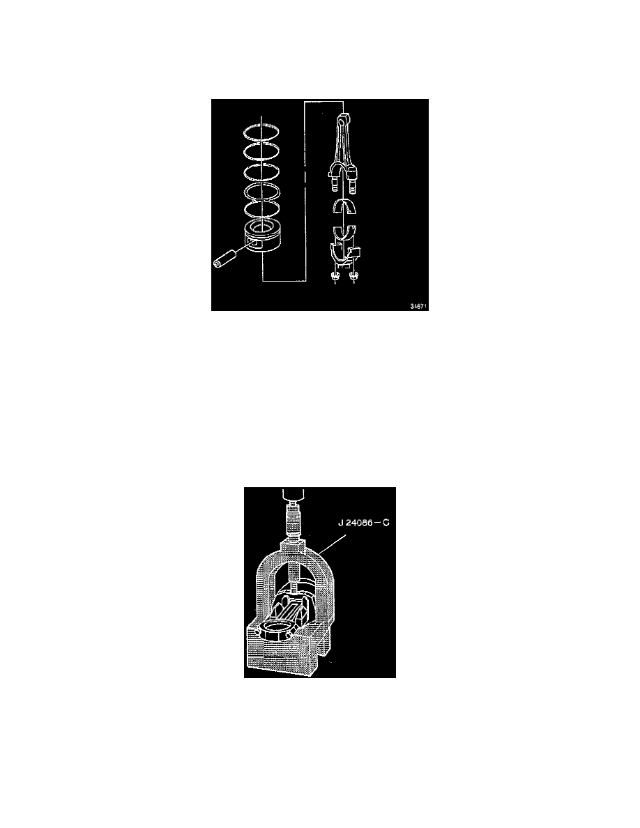
DISASSEMBLY
^
Tools Required
-
J 24086-C Piston Pin Removal Set, or equivalent
1. Remove the piston rings from the pistons.
2. Remove the pin from the piston.
ASSEMBLY
CAUTION: After the piston pin removal set (J 24086-C) installer hub bottoms on the support assembly, do not exceed 35000 kPa (5000 psi) or the
tool may be damaged.
NOTE: When assembling the piston and connecting rod, the mark on the top of the piston must point to the front of the engine block. The flange on the
connecting rod must face toward the front of the piston on the left hand assembly and face toward the rear of the piston on the right hand assembly.
1. Install the piston pin and connecting rod assembly.
a. Lubricate the piston holes in both the piston and the connecting rod assembly.
b. Press the piston pin into the piston and connecting rod assembly using the piston Pin removal set (J 24086-C).
c. Inspect for freedom of movement of the piston of the piston pin.
2. Install the piston rings onto the piston.
The marked side of the piston rings must face toward the top of the piston.
3. Use the following procedure in order to locate the piston ring gaps:
a. Install the oil ring spacer in the groove.
b. Hold the spacer ends together and properly locate the gap in order to install the lower oil ring rail.
c. Properly locate the gap and install the upper oil ring rail.
d. Flex the oil ring assembly to make sure the rings are free.