
S10/T10 P/U 2WD V6-4.3L VIN W (1997)
Most intermittents are caused by faulty electrical connections or wiring, although occasionally a sticking relay or solenoid can be a problem. Some items
to check are:
^
Poor mating of connector halves, or terminals not fully seated in the connector body (backed out).
^
Dirt or corrosion on the terminals. The terminals must be clean and free of any foreign material which could impede proper terminal contact.
^
Damaged connector body, exposing the terminals to moisture and dirt, as well as not maintaining proper terminal orientation with the component
or mating connector.
^
Improperly formed or damaged terminals. All connector terminals in problem circuits should be checked carefully to ensure good contact tension.
Use a corresponding mating terminal to check for proper tension. Refer to Checking Terminal Contact for the specific procedure.
^
The J 35616-A Connector Test Adapter Kit must be used whenever a diagnostic procedure requests checking or probing a terminal. Using the
adapter will ensure that no damage to the terminal will occur, as well as giving an idea of whether contact tension is sufficient. If contact tension
seems incorrect, refer to Checking Terminal Contact. See: General Troubleshooting Procedures/Checking Terminal Contacts
^
Poor terminal-to-wire connection. Some conditions which fall under this description are poor crimps, poor solder joints, crimping over wire
insulation rather than the wire itself, corrosion in the wire-to-terminal contact area, etc.
^
Wire insulation which is rubbed through, causing an intermittent short as the bare area touches other wiring or parts of the vehicle.
^
Wiring broken inside the insulation. This condition could cause a continuity check to show a good circuit, but if only 1 or 2 strands of a
multi-strand type wire are intact, resistance could be far too HI.
To avoid any of the above problems when making wiring or terminal repairs, always follow the instructions for wiring and terminal repair outlined under
the Repair Procedures.
Aftermarket Accessories
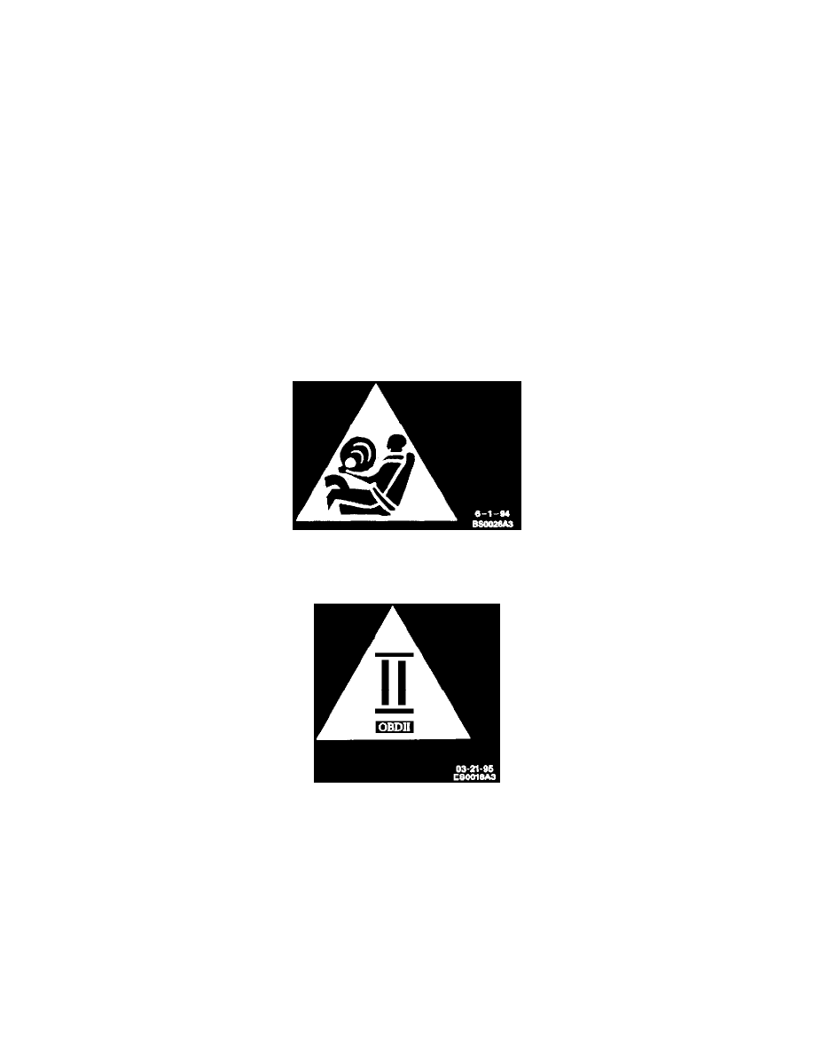
Do not tie aftermarket accessories into SIR circuits. All such circuits are indicated are indicated on circuit diagrams with the SIR symbol.
SIR Symbol
Do not tie aftermarket accessories into OBDII circuits. all such circuits are indicated on circuit diagrams with the OBDII symbol.
On Board Diagnostics II (OBDII) Symbol
Always check for aftermarket accessories (non-OEM) as the first step in diagnosing electrical problems. If the vehicle is so equipped, disconnect the
system to verify that these add-on accessories are not the cause of the problem.
Some possible causes of vehicle problems related to aftermarket accessories include:
1. Power feeds connected to points other than the Battery.
2. Antenna location.
3. Transceiver wiring located too close to vehicle electronic modules or wiring.
4. Poor shielding or poor connectors on antenna feed line.
Probing (Frontprobe & Backprobe)
After probing, when reconnecting connectors or replacing terminals, always be sure to reinstall Connector Position Assurance (CPA) and Terminal
Position Assurance (TPA).