
S10/T10 P/U 2WD V6-4.3L VIN W (1997)
Starter Motor: Testing and Inspection
Starter No Load Test
TOOLS REQUIRED
J39200 Digital Multimeter
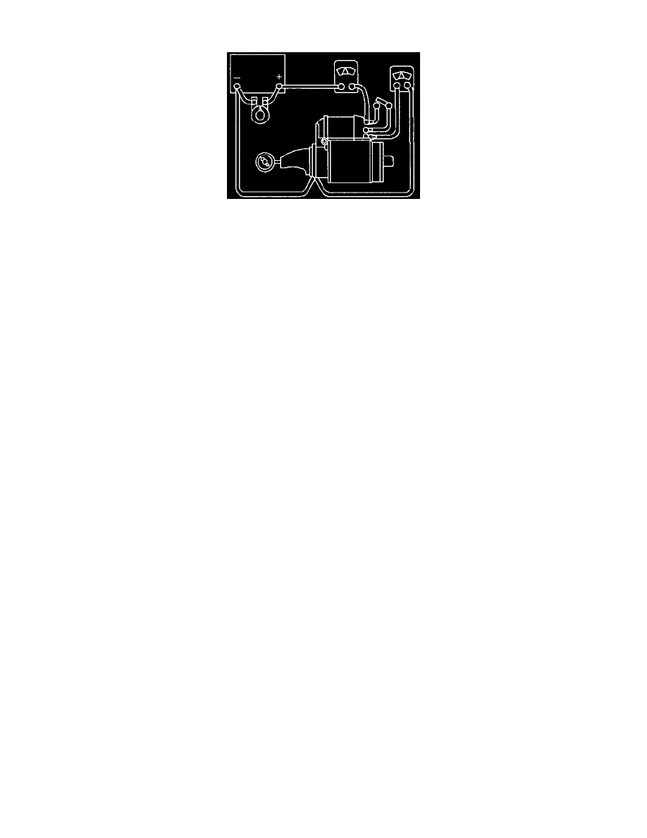
Before disassembling the starter motor for repair, do the following test:
1. Connect a voltmeter J39200 from the starter motor terminal to the starter motor frame (Ground), as shown.
2. Connect the starter motor and an ammeter in series, from the positive terminal of a fully charged 12 V battery.
3. Connect a switch, in the Open position, from the S terminal of the starter solenoid to the starter motor terminal.
Note: Never operate the starter motor for more than 30 seconds at a time. Allow it to cool for at least two minutes. Overheating, caused by too
much cranking, will damage the starter motor.
4. Also, hold an RPM indicator to the end of the armature shaft, in order to measure the speed.
5. Close the switch.
6. Compare the following measurements with the specifications.
-
The RPM (armature speed)
-
The current draw (Amps)
-
The battery voltage
7. If is not necessary to obtain the exact voltage as specified.
8. If the voltage is slightly higher, the RPM will be slightly higher, and the current (amps) will remain unchanged.
9. If the exact voltage is desired, connect a carbon pile across the battery to reduce the voltage to the specified value.
The test results indicate the following conditions:
1. Rated current draw (amps), and rated no-load speed (RPM).
This indicates the normal condition of the starter motor.
2. Low, no load speed (RPM) and high current draw (amps).
-
This could indicate too much friction, causing the armature to drag.
-
This can result from any of the following conditions:
-
Tight, dirty, or worn bearings
-
A bent armature shaft
-
Loose pole shoes
-
A grounded armature
-
Grounded fields
-
A shorted armature
-
These conditions can be checked further on a growler, after disassembly.
3. Failure to operate (no RPM), with high current draw (amps), indicates the following possible conditions:
-
A direct short to ground in the starter terminal or in the fields.
Seized bearings (This should have been noted by turning the armature by hand).
4. Failure to operate (RPM), with no current draw (amps), indicates the following conditions:
-
An open field circuit. This can be checked after disassembly by inspecting the internal connections and by tracing the circuit with a J34142-B.
-
An open circuit in the armature coils.
Inspect the commutator for badly burned bars, after disassembly.
-
Broken or weak brush springs