
S10/T10 P/U 2WD V6-4.3L VIN W (1997)
Alignment: Service and Repair
Front Wheel Alignment
Satisfactory vehicle operation may occur over a wide range of front wheel alignment settings. If the settings vary beyond certain tolerances, adjustments
are advisable. The "Specifications" at the back of this section are a guideline for vehicle diagnosis or for repairs.
Important: Set the front wheel alignment to specifications while the vehicle is in its normally loaded condition. Vehicles which are consistently operated
with heavy loads should have toe-in adjusted with the vehicle under heavy load. This procedure should result in longer tire life.
MEASURE FRONT ALIGNMENT ANGLES
-
Install alignment equipment according to the manufacturer's instructions.
-
Measure alignment angles and record the readings. If adjustments are required, make them in the following order: caster, camber, and toe-In.
CASTER AND CAMBER ADJUSTMENT
Important: Before adjusting caster and camber angles, the "Z" height setting on all four wheel drive and all wheel drive trucks must be inspected
before setting the alignment to specification. Refer to "Trim Height Specification."
Caster and camber adjustments are made by inserting shims between the upper control arm shaft and the frame bracket. Shims may be added, removed
or transferred to change the readings.
To adjust caster and camber, loosen the upper control arm shaft-to-frame nuts, add or remove shims as required and torque the nuts. Toe-in must be
checked after changing caster or camber.
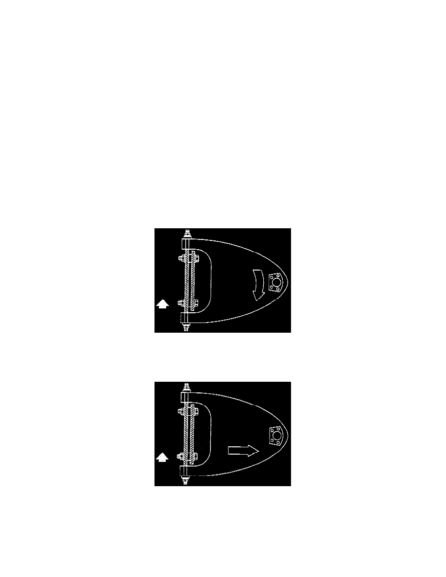
CASTER
-
Transfer shims from front to rear or rear to front.
-
The transfer of one shim from the rear-bolt to the front bolt will decrease positive caster.
CAMBER
-
Remove or add shims at both the front and rear of the shaft equally.
-
Adding an equal number of shims at both the front and rear of the cross shaft will decrease positive camber. A normal shim pack will leave at least
two threads of the bolt exposed beyond the nut. The difference between front and rear shim packs must not exceed 10.0 mm (0.40 inch). If these
requirements cannot be met, check for damaged control arms and related parts.
-
Tighten the nut on the thinner-shim pack first. This improves shaft-to-frame clamping force and torque retention.
TOE-IN ADJUSTMENT