
S10/T10 P/U 2WD V6-4.3L VIN X (1996)
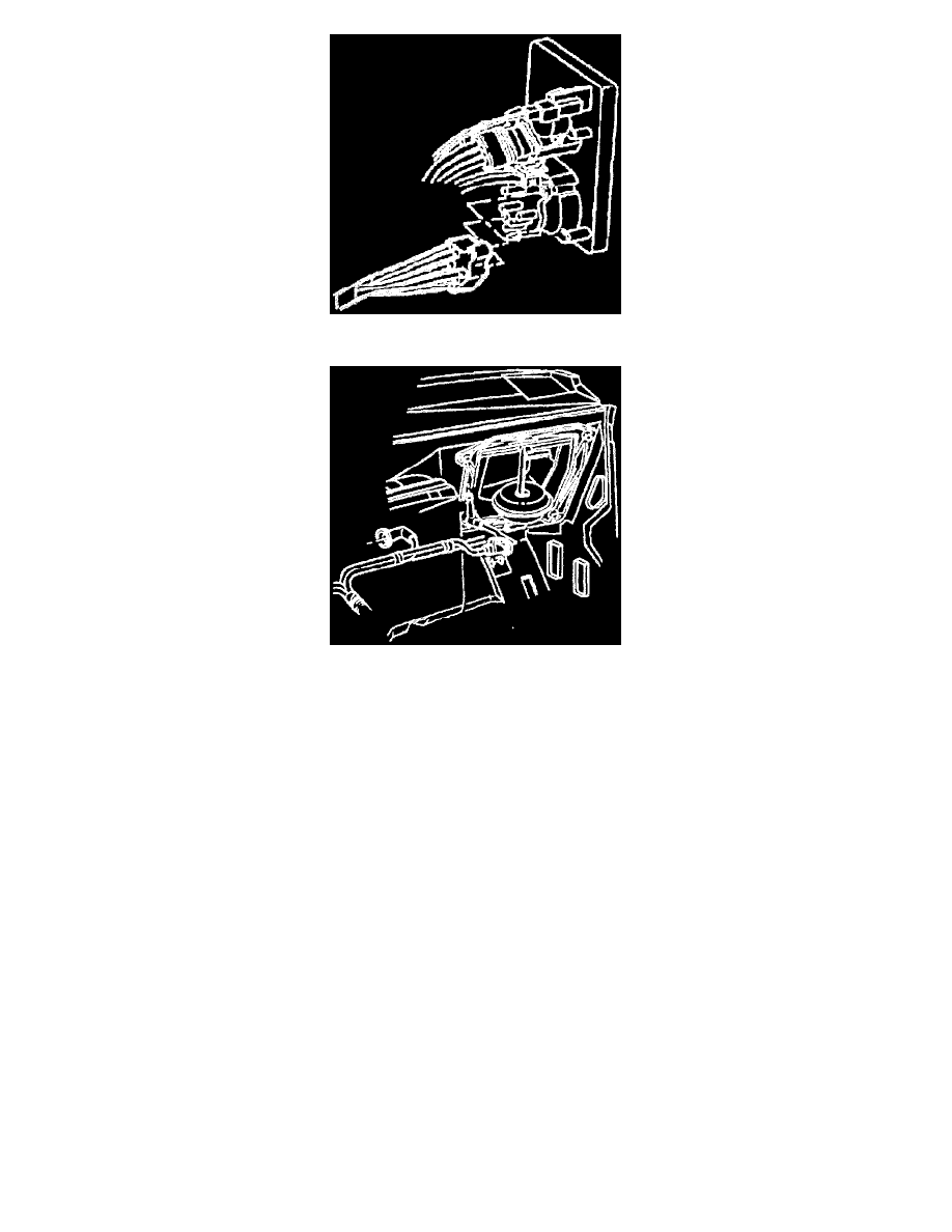
Vacuum Harness To The Rotary Valve
Vacuum Harness To The Air Inlet Valve
VACUUM SYSTEM
Ports on rotary vacuum valves are illustrated to provide simplicity in following vacuum schematic lines but are numbered in consecutive order on the
actual valve (refer to accompanying images).
Start the engine and allow it to idle. Move the rotary knob to each position and refer to the vacuum diagrams and operational charts for airflow, air door
functioning, and vacuum circuits. If airflow is not out of the proper outlet at each rotary knob position do the following:
Inspect
1. The hose connections at the vacuum actuator's, control head valve, and vacuum tank.
2. The vacuum source circuit:
-
Install a vacuum tee and gage (with restrictor) at the vacuum tank outlet. Idle the engine and read the vacuum. At all selector lever positions,
normal vacuum is equivalent to manifold vacuum.
-
If vacuum is less than normal at all positions, remove the tee and connect the vacuum gage line to the tank and read the vacuum. If still low,
then the problem lies in the feed circuit, the feed circuit to the tank or in the tank itself. It vacuum is now normal, then the problem lies
downstream.
-
Vacuum may be less than normal at some positions. If- vacuum was low at one or several of the selector lever positions. a leak is indicated in
these circuits.
-
Vacuum may be normal at all positions. If vacuum was normal and even at all positions, then the malfunction may be caused by improperly
connected or plugged or split lines or a malfunctioning vacuum valve or valves.
3. Specific vacuum circuit check: