
S10/T10 P/U 2WD V6-4.3L VIN X (1996)
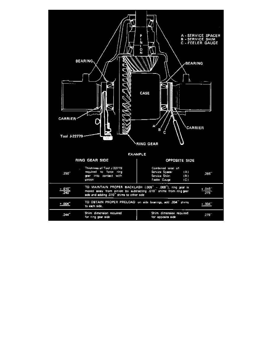
Fig. 14 Side Bearing Preload Adjustment.
4. With ring gear tight against pinion (zero to 0.001 inch backlash), insert gauging tool No. J-22779, or equivalent, between left bearing race and
housing,
Fig. 14.
5. While oscillating tool, turn adjusting nut clockwise to force ring gear toward pinion until noticeable drag on tool can be felt, then tighten lock bolt
on side of tool.
6. Insert a 0.170 inch service spacer between right bearing cap and housing, then select and install service shim that will easily slip between spacer
and housing.
Do not reuse cast iron production shims as they may crack during installation. If service spacers and shims were previously
installed, they can be reused.
7. Insert progressively thicker feeler gauges between housing and service shim until slight drag can be felt when inserting gauge. Thickness of feeler
gauge used to produce slight drag will be dimension C used in
Fig. 14, to determine shim thickness.
8. Remove service spacer and shim, and gauge tool, without disturbing adjustment of tool.
9. Measure thickness of gauging tool at a minimum of three positions, average measurements and record average.
10. Add thicknesses of service spacer (A), shim (B) and feeler gauge (C),
Fig. 14, and record sum.
11. Apply dimensions obtained in steps 9 and 10 calculation shown in
Fig. 14, to determine proper left and right shim thicknesses.
12. Install shim selected for left side first, then wedge right shim between bearing race and service spacer.
Position shims so that chamfer is toward
outside. If chamfer in right shim is not sufficient to allow installation without damaging spacer, grind or file chamfer prior to installation.
If difficulty is encountered installing right shim, partially remove case, insert shim, slide shim and case into position, then seat shim using
soft-faced hammer while rotating differential case.
13. Install bearing caps and tighten bolts to specifications, then check and adjust backlash as needed.