
Silverado 3500 4WD V8-8.1L VIN G (2006)
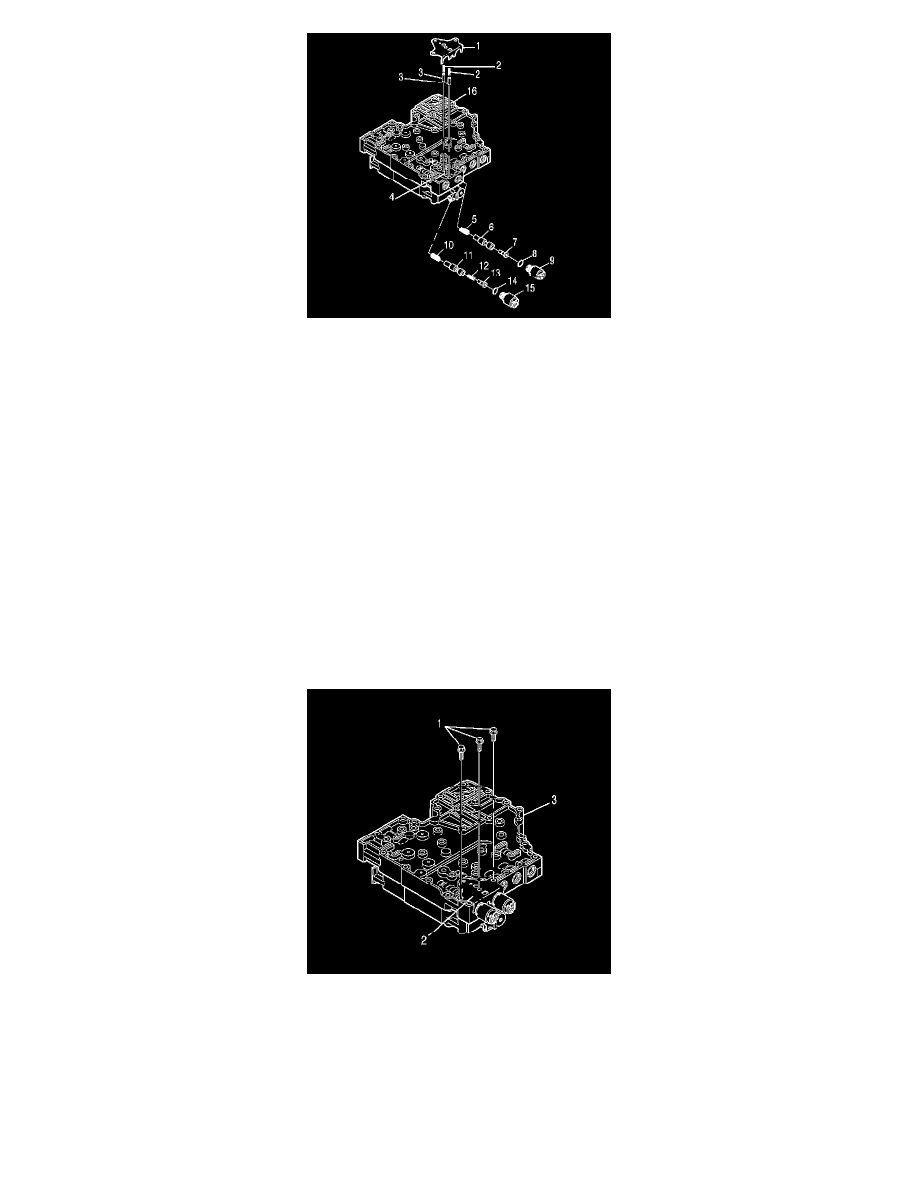
13. Position the control valve assembly on the work table so that main valve body (16) is facing up.
14. Install the solenoid O-ring (14) onto the PCS1 (15).
Important: P/N 29541895 is printed on the pressure control solenoid 1 (PCS1).
15. Install the solenoid O-ring (8) onto the PCS2 (9).
Important: P/N 29541896 is printed on the pressure control solenoid 2 (PCS2).
16. Install the spring (10), PCS1 trim valve (11), spring (12), and trim gain valve (13).
17. Install the spring (5), PCS2 trim valve (6) and trim gain valve (7).
18. Install PCS1 (15) so that the electrical connection faces up. Do not seat the solenoid.
19. Install PCS2 (9) so the electrical connection faces up. Do not seat the solenoid.
20. Align 2 accumulator plugs (3) so that the spring bores face up.
21. Install 2 accumulator plugs (3) and 2 accumulator springs (2).
22. Push PCS1 and PCS2 into the bores until the solenoids seat.
23. Align the PCS retaining bracket (1) with main valve body locating pin (4).
24. Install the PCS retaining bracket (1) so that PCS1 and PCS2, the accumulator plugs, and the accumulator springs are retained against the valve
body.
25. Install 3 bolts (1) retaining the PCS retaining bracket (2).
^
Tighten bolts (1) to 12 Nm (108 inch lbs.).
Notice: Refer to Fastener Notice in Service Precautions.