
Silverado Classic 1500 4WD V8-5.3L Hybrid (2007)
Install the J 46093 (1) and bolts. The flange on J 46093 should locate into the hole in the flexplate. Use 2 M10 1.5 x 40 mm bolts for proper tool
operation.
Tighten the bolts to 50 Nm (37 ft. lbs.).
7. Remove the crankshaft balancer bolt. Do not discard the crankshaft balancer bolt. The balancer bolt will be used during the balancer installation
procedure.
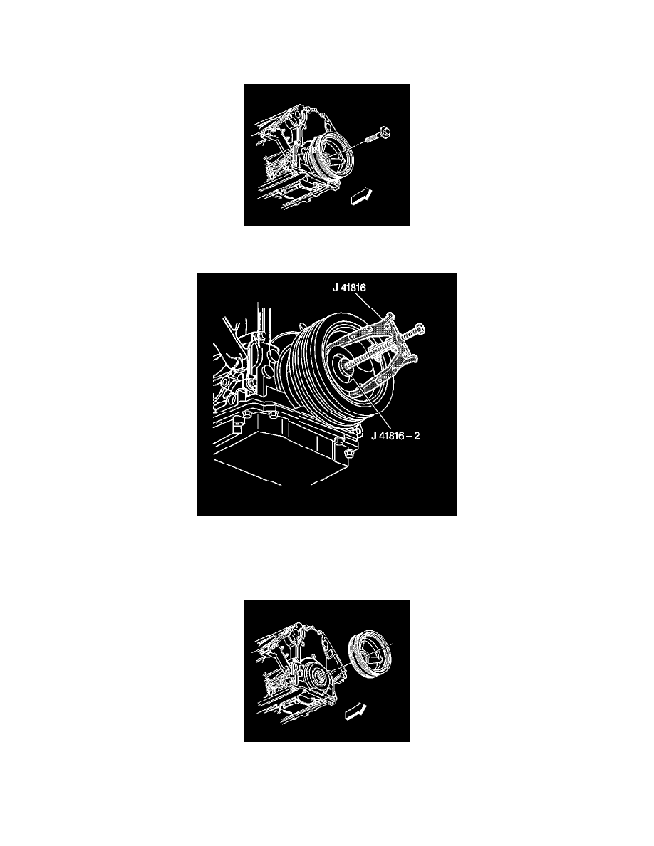
8. Use the J 41816 and J 41816-2 in order to remove the crankshaft balancer.
9. Remove the J 41816 and the J 41816-2 from the crankshaft balancer.
10. Clean and inspect the crankshaft balancer. Refer to Crankshaft Balancer Cleaning and Inspection.
Installation Procedure
1. Important:
^
Make sure that the teeth of J 42386-A mesh with the teeth of the engine flywheel.
^
The used crankshaft balancer bolt will be used only during the first pass of the balancer installation procedure. Install a NEW bolt and tighten
as described in the second, third, and forth passes of the balancer bolt tightening procedure.
^
The crankshaft balancer installation and bolt tightening involves a 4-stage tightening process. The first pass ensures that the balancer is