
Spectrum L4-91.5 1.5L (1985)
3.
Using a suitable chisel, bend back staked portion of locking washer between inner tie rod and rack.
4.
Remove tie rod from rack.
5.
Disconnect right and left pipe assemblies between valve housing and cylinder.
6.
Loosen adjusting plug nut, then remove spring and rack bearing.
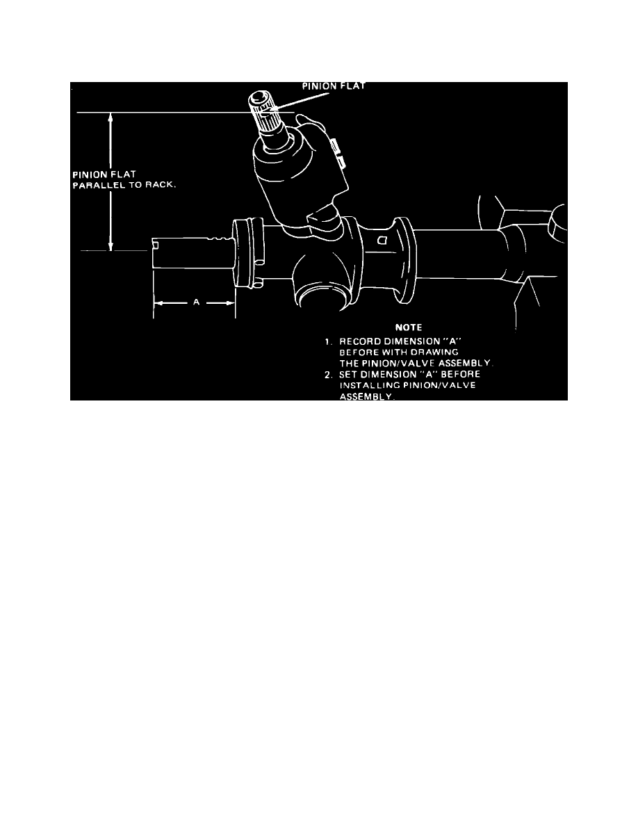
Fig. 5 Measuring & centering rack/pinion
7.
Rotate pinion gear until pinion flat is parallel or aligned to the rack assembly. Carefully measure dimension A, Fig. 5. Record reading. This
relationship must be used for assembly.
8.
Remove valve/pinion housing assembly.
9.
Remove adjusting shims and retaining ring.
10.
Withdraw rack assembly and seal holder together.
11.
Remove inner rack seal and shock dampener.
12.
Remove piston and O-ring seals from rack.
13.
Remove valve assembly from housing.
14.
Remove bearing and seal from valve housing.
15.
Remove snap ring from spool end of valve assembly, then slide spool, seals and spacer. Do not remove Teflon seals.
ASSEMBLY
1.
Install spacer, then slide oil seal onto shaft.
2.
Install valve spool.
3.
Install snap ring on to shaft at spool.
4.
Install upper bearing and seal into valve housing.
5.
Before installing pinion/valve assembly into valve housing.
6.
Place tool J-33997-10 or equivalent, onto upper pinion shaft.
7.
Install pinion/valve assembly into valve housing.
8.
Install seal onto rack piston.
9.
Lubricate rack gear surfaces. Install seal into seal holder with flat end of seal in first, then install seal holder.
10.
Install shock damping ring.
11.
Install inner rack seal with flat end of seal facing away from rack piston.
12.
Install rack assembly and push seal holder into housing.
13.
Install retaining ring.
14.
Move rack assembly into housing as far as it will go and measure distance between end of holder and tip of rack shaft. The seals are positioned
correctly when dimension L is .39 inch (10 mm) or more.