
Suburban 1/2 Ton 4WD V8-379 6.2L DSL (1986)
Refer to Figure No. 1 for Axle Shaft and Housing Detail.
After performing brake work ensure brake system is operational before returning the vehicle to the owner.
All involved trucks are equipped with an 8.5" ring gear semi-floating rear axle. Refer to Section 4B, Rear Axle, and Section 5, Brakes, of the 1986 Light
Duty Service Manual (ST-330-86) for further removal or installation instructions.
1.
Place transmission in neutral.
2.
Lift and support vehicle.
3.
Remove tires from rear axle.
4.
Remove and discard brake drums.
5.
Disconnect the parking brake cables at the equalizer.
6.
Remove differential cover and catch the oil in a drain pan.
7.
Disconnect the brake line at the wheel cylinders and catch the fluid in a drain pan.
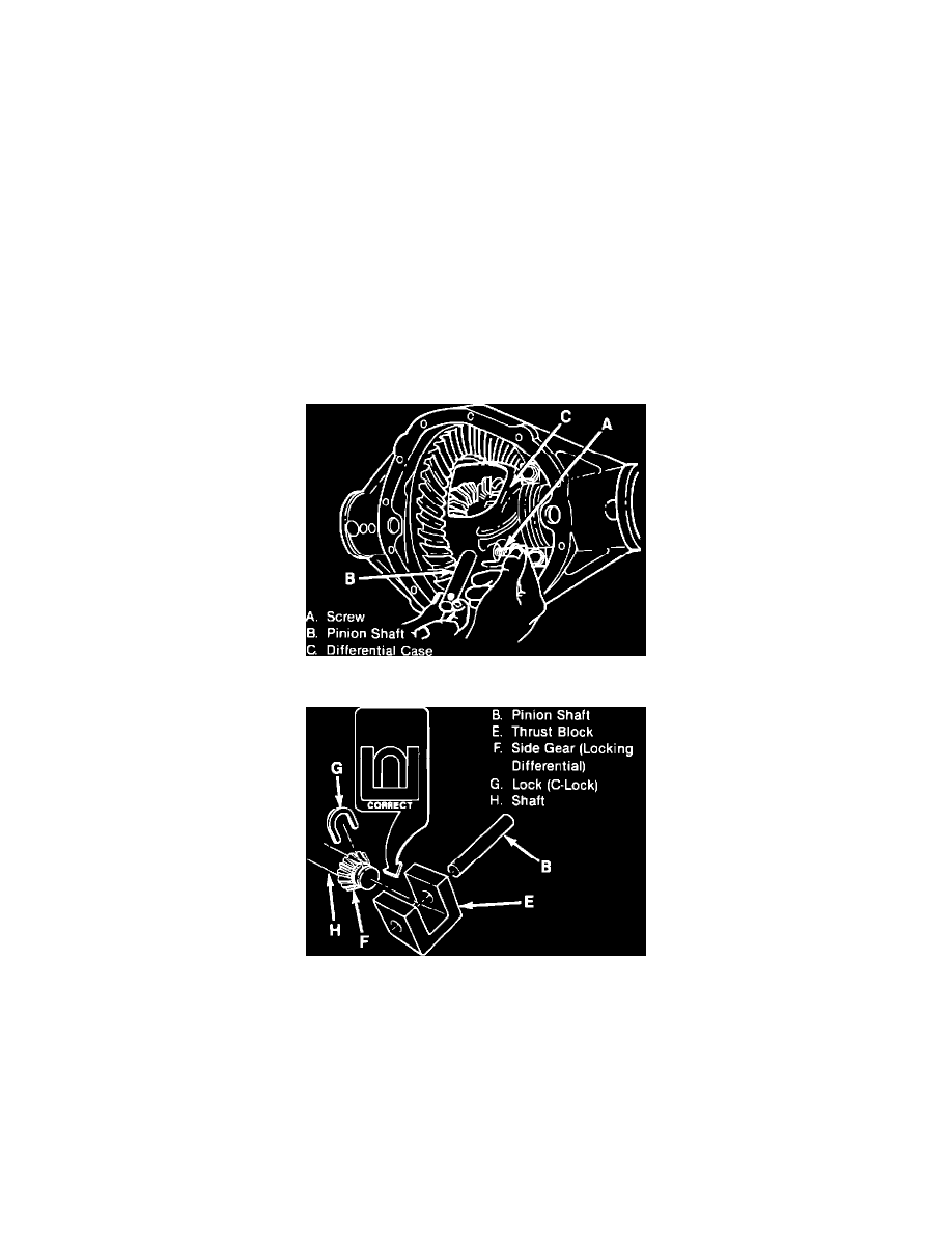
FIGURE 2 - DIFFERENTIAL ASSEMBLY
FIGURE 3 - PINION SHAFT ASSEMBLY
8.
Remove screw (A), pinion shaft (B), and "C"-lock (G) from the differential case, Figures No. 2 and No. 3.
9.
Withdraw axle shafts and set aside.
10.
Remove and discard the complete brake assemblies. This includes the backing plate, attaching hardware and parking brake cable.
11.
Install new brake assemblies on the axle. Torque backing plate bolts to 47 N-m (35 ft.lbs.).
12.
Reconnect brake line to the wheel cylinders. Torque to 18 N-m (160 in. lbs.).
13.
Reinstall axle shafts.