
Tracker 4WD L4-1.6L VIN 6 (1998)
Hydraulic Control Assembly - Antilock Brakes: Service and Repair
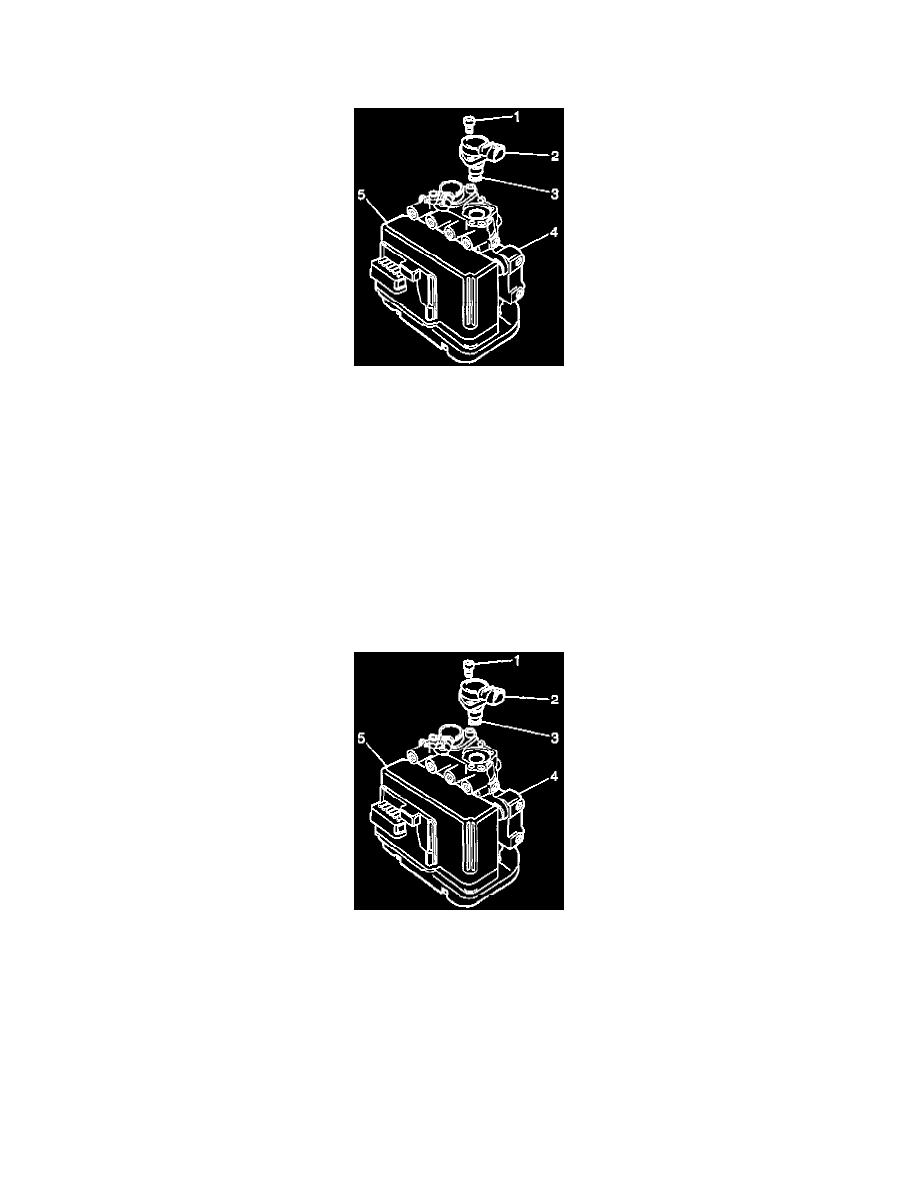
RREMOVAL PROCEDURE
1. Disconnect the Brake Solenoid Valve Electrical connector.
2. Remove the Torx head bolts (1).
3. Remove the Solenoid (2).
IMPORTANT: Verify that the brake solenoid valve lip seal (3) is still attached to the brake solenoid valve (2) when removing the brake solenoid
valve. If the seal is not attached, inspect the brake solenoid valve bore in the brake modulator.
IMPORTANT: Do not attempt to disassemble the brake solenoid valve. The brake solenoid valve is serviceable only as an assembly.
INSTALLATION PROCEDURE
NOTICE: The use of rubber hoses or parts other than those specified for the Antilock Brake System (ABS) may lead to functional problems requiring
replacement of the hydraulic parts. Replace all components included in repair kits used to service this system. Lubricate rubber parts with clean, fresh
brake fluid to ease assembly. Do not use lubricated shop air on brake parts as damage to rubber components may result. If any hydraulic component is
removed or brake line disconnected, it is necessary to bleed the entire brake system. The fastener tightening specifications are for dry, Unlubricated
fasteners.
1. Use the following procedure in order to install the brake solenoid valve lip seal (3):
1.1.Lubricate the seal on the new brake solenoid valve with clean brake fluid.
1.2.Verify that the brake solenoid valve lip seal is properly positioned before installing the brake solenoid valve in the ABS brake modulator.
2. Position the brake solenoid valve (2) so that the brake solenoid valve electrical connector will face the same direction before it was removed.
3. By hand, press down firmly on the brake solenoid valve (2) until the brake solenoid valve flange seats on the ABS brake modulator.
4. Install the Torx(R) head bolts (1).
^
Tighten the solenoid Torx (R) head bolts to 5 Nm (44 inch lbs.).
NOTICE: Always use the correct fastener in the proper location. When you replace a fastener, use ONLY the exact part number for that
application. The manufacturer will call out those fasteners that require a replacement after removal. The manufacturer will also call out the
fasteners that require thread lockers or thread sealant. UNLESS OTHERWISE SPECIFIED, do not use supplemental coatings (paints, greases, or