
Tracker 4WD L4-1.6L VIN 6 (1998)
3. Install the four fluid pipes in the following order: 8, 4, 6 and then 7.
4. Install the new transmission fluid pan gasket and the transmission fluid pan to the transmission.
IMPORTANT: Ensure the filler tube is properly connected when installing the transmission pan.
5. Secure the transmission fluid pan with the fourteen bolts.
^
Tighten the transmission fluid pan bolts to 5 Nm (44 inch lbs.).
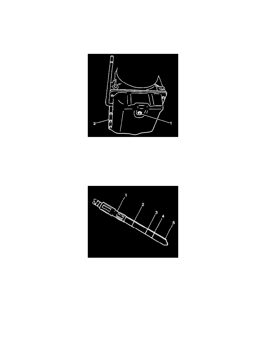
6. Install the transmission drain plug (1) into the transmission.
^
Tighten the transmission drain plug to 17 Nm (13 ft. lbs.).
7. Install the propeller shaft into the vehicle aligning the index marks made during the front propeller shaft removal (four-wheel drive models).
8. Secure the front propeller shaft with four bolts and four nuts.
^
Tighten the front propeller shaft bolts and nuts to 50 Nm (37 ft. lbs.).
9. Lower the vehicle.
10. Refill the transmission as necessary using the following steps:
10.1.
Place the vehicle on a level surface.
10.2.
Remove the fluid level indicator.
10.3.
Add approximate 1.5 liters (1.6 quarts) of Dexron (R) III automatic transmission fluid GM P/N 12346143, or the equivalent, into the fluid
filler tube.
10.4.
Install the fluid level indicator into the fluid filler tube.
10.5.
Apply the parking brake and block the vehicle wheels.
10.6.
With the selector lever in the PARK position, start the engine. DO NOT race the engine.
10.7.
Run the engine at idle speed.
10.8.
Move the selector lever through each range and return the selector lever to the PARK position.
10.9.
While the engine is running at idle remove the fluid level indicator from the filler tube and wipe the indicator off.
10.10. Reinsert the fluid level indicator into the filler tube making sure it is seated in its original position.
10.11. Remove the indicator and check the fluid level. The level should be between the FULL HOT (2) and the LOW HOT (3) marks. If the level
is below the LOW HOT mark, add fluid to bring the level to the FULL HOT mark. Bringing the fluid level from the LOW HOT mark to